Removal of the inhibiting bits
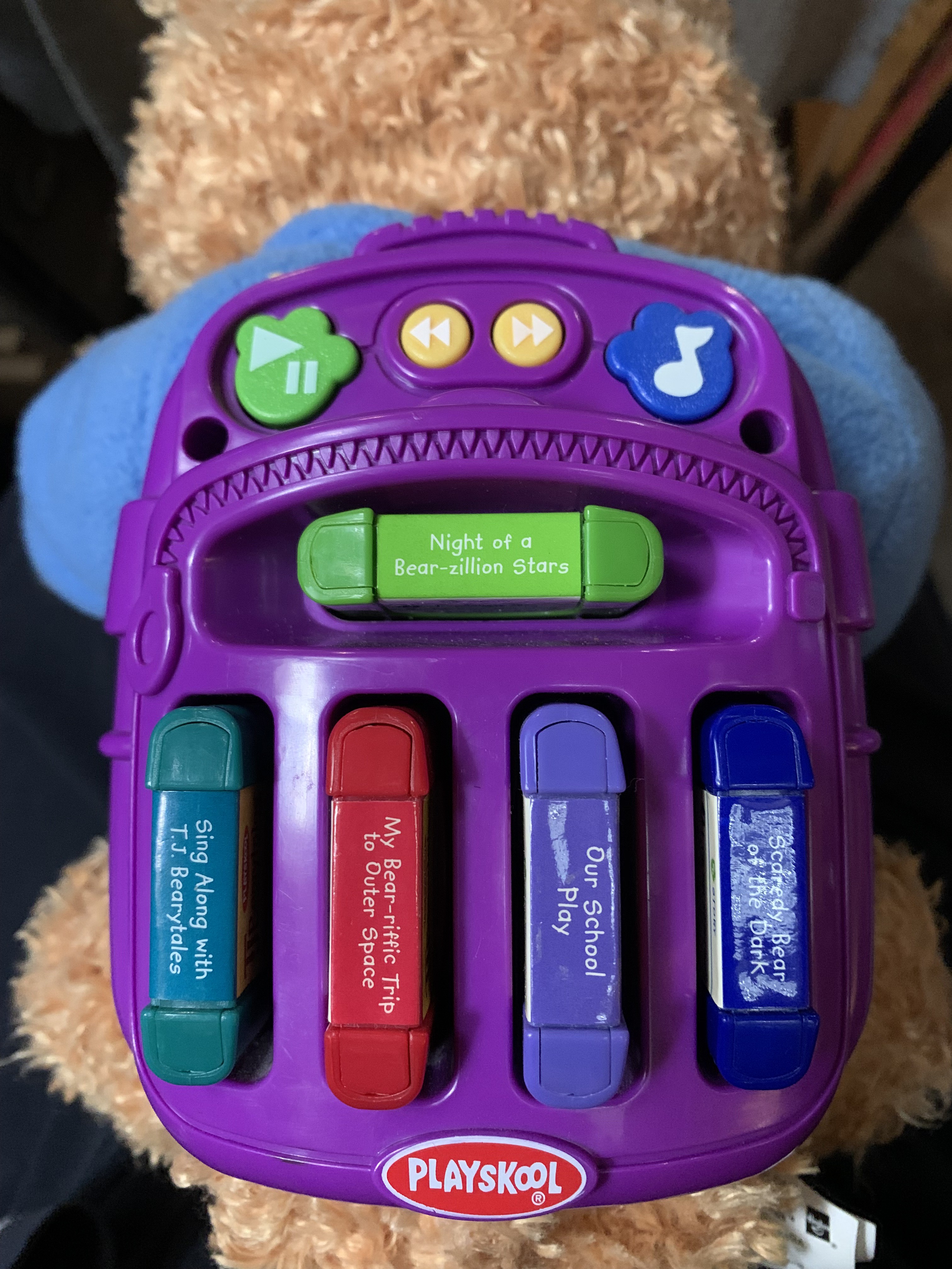
We took off TJ's plastic backpack to get at the board. The backpack is secured with four size 2.3 triangle security screws. Once the backpack lifts off, the board is exposed.
 |  |
Mapping the connections on the board
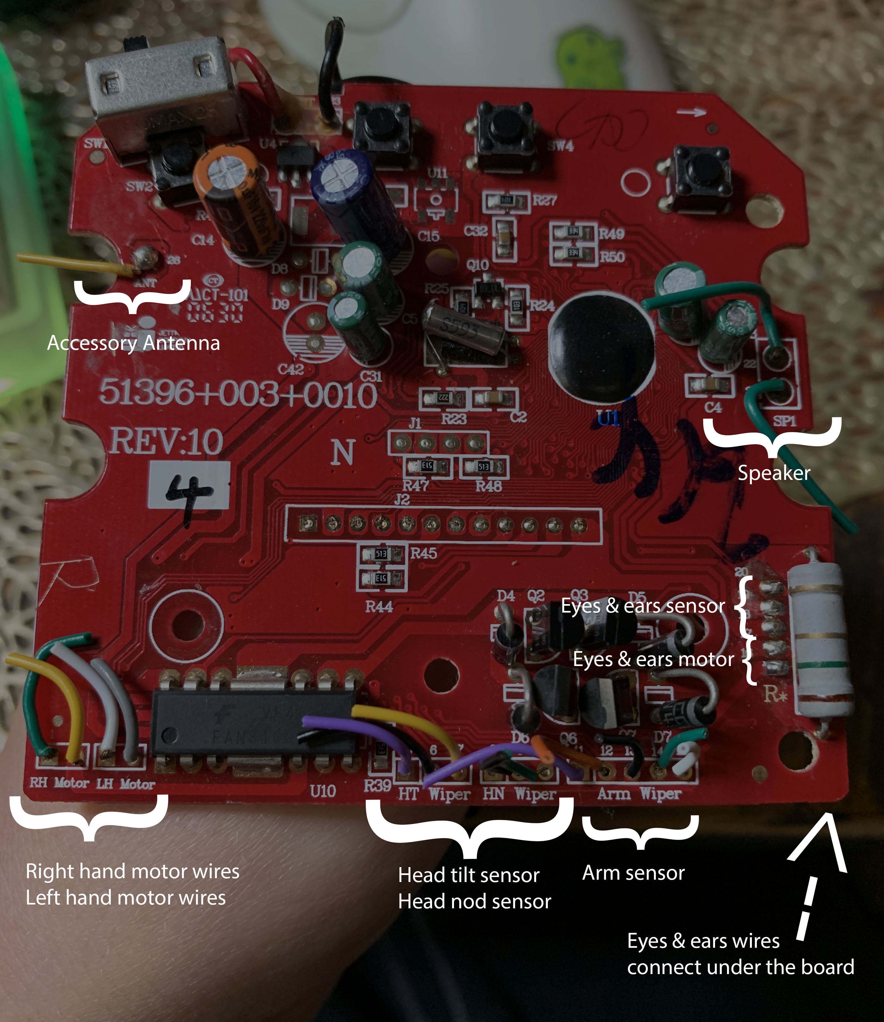
The board is screwed in with two Philips head screws and tips out along the bottom edge. We disconnected and cut the wires leading to TJ's various parts. Below is a photo of the board with its original wires, most of which are clearly labeled.

The wires are listed by pin number in the table below.
| Pins | Use | Color |
|---|---|---|
| 1 | Right Hand Motor A | Green |
| 2 | Right Hand Motor B | Yellow |
| 3 | Left Hand Motor A | White |
| 4 | Left Hand Motor B | Gray |
| 5 | Head Turn Sensor A | Purple |
| 6 | Ground | Black |
| 7 | Head Turn Sensor B | Yellow |
| 8 | Head Nod Sensor A | Red |
| 9 | Ground | Black |
| 10 | Head Nod Sensor B | Green |
| 11 | Left Arm Sensor A | Purple |
| 12 | Left Arm Sensor B | Orange |
| 13 | Ground | Black |
| 14 | Right Arm Sensor A | Green |
| 15 | Right Arm Sensor B | White |
| 16 | Eyes & Ears Motor A | Purple |
| 17 | Eyes & Ears Motor B | Blue |
| 18 | Eyes & Ears Sensor A | Orange |
| 19 | Ground | Black |
| 20 | Eyes & Ears Sensor B | Gray |
| 21 | Speaker A | Green |
| 22 | Speaker B | Green |
| 26 | Accessory Antenna | Yellow |
 Mx. Jack Nelson
Discussions
Become a Hackaday.io Member
Create an account to leave a comment. Already have an account? Log In.