 Keith
KeithPin 1 isolated from 5V, then wired to A14 (pin 1 of RAM)
Pin 27 isolated from A14 (pin 1 of RAM), then wired to /WE (pin 27 of RAM).
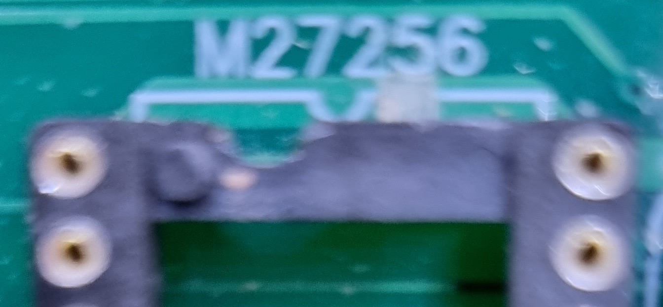
Cut track on top side of board, from ROM pin 1 to pin 28 (VCC):
Next make the mods shown below:
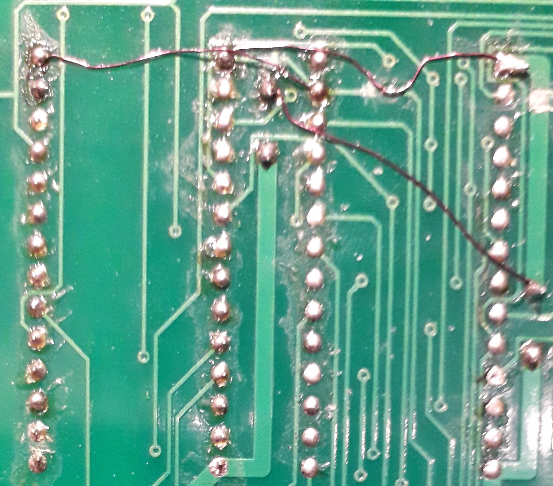
The RAM is on the left, the ROM on the right. Note:
ROM pin 27 track cuts each side.
The track joining pins 1 joins the A14 track.
The ROM pin 27 is tied to RAM pin 28 (VCC), not 27 (/WE). The latter connection will cause the CPU to corrupt the ROM even if the code never tries to write to EEPROM addresses.
Discussions
Become a Hackaday.io Member
Create an account to leave a comment. Already have an account? Log In.