lion mclionhead
-
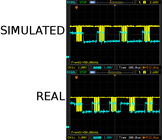
Simulated flash
12/10/2022 at 23:31 • 0 commentsThe next step was simulating the flash for the camera. The journey begins with driving the DAC connected to D1 to simulate the "from flash" signal. Apparently, it expects D1 to be held on the last bit for a while, then lowered for a while to signify busy, then raised as a form of flow control.
Helas, the packets from the camera are not constant length as they were when using the real flash. There are insertions, deletions, & transpositions. It somehow knows the flash is simulated despite getting a byte for byte replica.
![]()
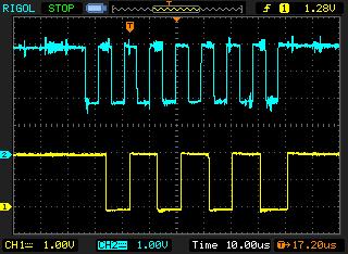
The real flash has variations in the length of its busy period but it actually looks like the camera has a minimum break between bytes. It was confirmed to definitely wait for the CLK to go low & high by simulating very long busy periods.
![]()
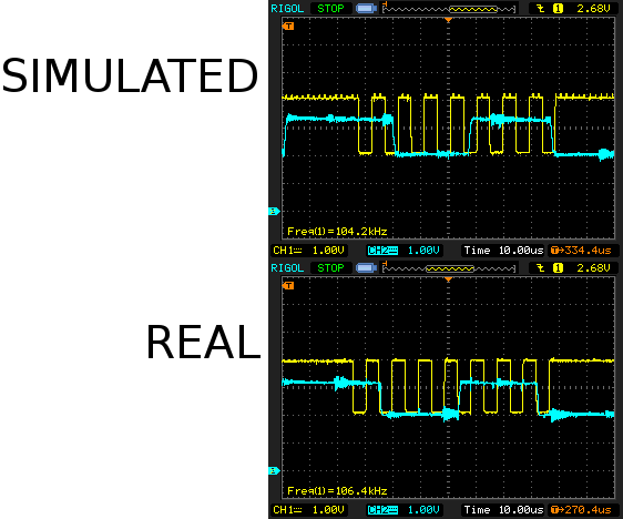
But more importantly, the real flash has transitions right on the falling edge while the simulated flash is right against the rising edge. It's probably seeing data corruption from the simulated flash. The simulated flash reads back its own data using its own delayed ADC so it doesn't see the data corruption.
![]()
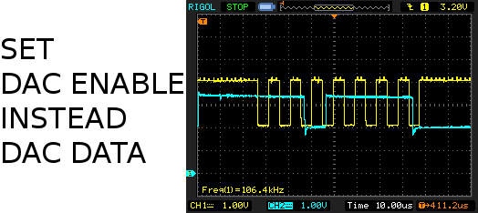
Then a lion realized it might be faster to flip the GPIO between analog & digital to get it to change between 2V & 3V faster. This is only possible on the STM32 by enabling & disabling the DAC. This did indeed buy just enough time to eliminate the glitches. It actually went through the full metering & exposure with simulated packets. More margin could be bought with overclocking.
![]()
An electronically simulated flash was a big step towards wireless, converting a vintage flash to ETTL, & building custom flashes. The next step is simulating the camera for the flash.
-
Timing & camera settings
12/09/2022 at 19:44 • 0 commentsGot some more packets with timing values for key bits.
8e/ff 8e/b5 de/4c 8e/e5 0d/ff 8e/a9 91/25 8e/a1
2b/f8 2b/a5 00/2c 8e/b9 00/80 8e/bd 18/00 69/23
23/99 ff/fb 02/ff 8e/f9 55/ff 8e/f7 7b/ff 8e/b3
00/12 00/46 00/2f 00/f5 57/ff 49/ff 5c/ff 0f/ff
00/be 8e/14 8e/bb 00/48 00/ff 8e/e6 3f/ff 10/ff
00/ff 8e/b7 8e/38 8e/b8 8e/6d 8e/b4 8e/1d 8e/a8
91/00 8e/a5 00/2d
X 0V 100uS

X 3.3V 400uS
8e/a5 01/2c
PACKET SIZE: 53 96000uS
8e/ff 8e/b5 de/4c 8e/e5 0d/ff 8e/a9 91/25 8e/a1
2b/f8 2b/a5 00/2c 8e/b9 00/80 8e/bd 18/00 69/23
23/99 ff/fb 02/ff 8e/f9 55/ff 8e/f7 7b/ff 8e/b3
00/12 00/46 00/2f 00/f5 57/ff 49/ff 5c/ff 0f/ff
00/be 8e/14 8e/bb 00/48 00/ff 8e/e6 3f/ff 10/ff
00/ff 8e/b7 8e/38 8e/b8 8e/6d 8e/b4 8e/1d 8e/a8
91/00 8e/a5 00/2d
X 0V 100uS

X 3.3V 400uS
8e/a5 01/2c
PACKET SIZE: 53 24000uS
8e/ff 8e/b4 8e/1d 8e/f2 c0/ff 8e/ff 8e/b4 8e/03
8e/f2 a0/ff 8e/b0 8e/80 8e/b1 8e/04 8e/b3 00/12
00/46 00/2f
PACKET SIZE: 18 64000uS
00/b4 8e/23
CLK 0V 24000uS

CLK 3.3V 30000uS

PACKET SIZE: 2 30000uS
7f/ff 8e/b3 00/32 00/46 00/2f 00/f8 3a/ff 8e/bb
00/48 00/ff 8e/b7 8e/38 8e/b8 8e/6d 8e/b0 8e/88
8e/b4 8e/1d 8e/f2 c0/ff 8e/b3 00/36 00/46 00/2f
00/b4 8e/3d
CLK 0V 16000uS

X 0V 20000uS

X 3.3V 30000uS

CLK 3.3V 40000uS


PACKET SIZE: 26 40000uS
7f/b4 8e/1d 8e/b3 00/12 00/46 00/2f 00/fc 88/ff
c0/ff 1a/ff 2a/ff 85/ff 78/ff

8e/ff 8e/b5 de/4c
8e/e5 0d/ff 8e/a9 91/25 8e/a1 2b/f8 2b/a5 00/2c
8e/b9 00/80 8e/bd 18/00 69/23 23/99 ff/fb 02/ff
8e/f9 55/ff 8e/f7 7b/ff 8e/b3 00/12 00/46 00/2f
00/f5 57/ff 49/ff 5c/ff 0f/ff 00/be 8e/14 8e/bb
00/48 00/ff 8e/e6 3f/ff 10/ff 00/ff 8e/b7 8e/38
8e/b8 8e/6d 8e/b4 8e/1d 8e/a8 91/00
The timing values are uS since the last byte.
The minimum time before a packet is
90ms before 8e/ff 8e/b5 metering
20ms before 8e/ff 8e/b4 preflash
20ms before 7f/ff 8e/b3 mane flash
There's no delay between the mane flash 2a/ff 85/ff 78/ff & next metering packet 8e/ff 8e/b5
This is actually a separate packet which occurs after metering repeat, power on, metering start:
8e/a5 00/2d

X 0V 66uS
X 3.3V 237uS

8e/a5 01/2c
There's no delay before it & it doesn't always occur.
There's up to a 60ms delay in the preflash packet before 00/b4 8e/23.
Time between the preflash packet & preflash trigger CLK 0V is 20ms at minimum.
Time between the mane flash packet & mane flash trigger CLK 0V is 16ms at minimum.
Then the time between CLK 0V & X 0V is 1ms at minimum.
X is held down for the duration of the shutter speed.
For 2nd curtain sync, the trigger starts up reversed. X fires 1st, then CLK is fired at the end of the exposure.
MANE FLASH1 235uS
7f/ff 8e/b3 00/32 00/46 00/2f 00/f8 26*/ff 8e/bb
00/48 00/ff 8e/b7 8e/50* 8e/b8 8e/38* 8e/b0 8e/a2*
8e/b4 8e/1d 8e/f2 c0/ff 8e/b3 00/36 00/46 00/2f
00/b4 8e/3d
X 0V 22704uS

CLK 0V 1005237uS

X 3.3V 1017336uS

CLK 3.3V 1023915uS

MANE FLASH2 225uS
Eventually, the protocol was divided into 9 discrete packets identified by 1-4 starting bytes
?? b5 4c ff POWERON
?? b5 4c e5 METERING1
a5 METERING2
?? b4 PREFLASH1
b4 23 PREFLASH2
?? b3 MANE FLASH1
b4 1d MANE FLASH2
b4 25 FAST FLASH
bb MANUAL FLASH
Shutter speeds of 1/200 & above introduce an extra b4 25 after MANE FLASH1 & show the high speed icon in the camera LCD.
The next step was putting reference captures of all the packets in the firmware & beginning to parse the variable bits. This was the beginning of yet another long slog through corner cases.
POWERON:
offset 15,38 FROM FLASH: exposure compensation
18=-3
15=-2 2/3
13=-2 1/3
10=-2
0d=-1 2/3
0b=-1 1/3
08=-1
05=-2/3
03=-1/3
00=none
fd=+1/3
fb=+2/3
f8=+1
f5=+1 1/3
f3=+1 2/3
f0=+2
ed=+2 1/3
eb=+2 2/3
e8=+3
offset 18 TO FLASH: focal length in mm Max 255
offset 38 TO FLASH: ISO code
48=100
50=200
58=400
60=800
68=1600
70=3200
88=25,600
8d=40,000
offset 42 FROM FLASH: mode code. These values are only for 90 deg.
00=ETTL
01=manual slow speed
08=ETTL 2nd curtain
09=manual 2nd curtain
10=ETTL high speed
11=manual high speed
12=multi
offset 45 TO FLASH: aperture code
16=1.8
20=2.8
30=5.6
38=8.0
50=22
offset 47 TO FLASH: shutter speed code 1 truncated to 73
METERING1:
offset 12 FROM FLASH: exposure compensation code
offset 15 TO FLASH: focal length in mm Max 255
offset 16 FROM FLASH: focal length flash is set to. Limited to 105
offset 35 TO FLASH: ISO code
offset 39 FROM FLASH: mode code
offset 42 TO FLASH: aperture code
offset 44,46 TO FLASH: shutter speed code 1 & 2
shutter speed code 1 & 2:
38 1d=1s
48 1d=1/4
65 1d=1/50
6d 1d=1/100
73 1d=1/160
75 05=1/200
78 05=1/250
80 05=1/500
88 05=1/1000
93 05=1/4000
PREFLASH1:
offset 2 TO FLASH: shutter speed code 2
offset 4 FROM FLASH: shutter speed code response
c0=1/160 & below
a0=1/200 & above
offset 11 TO FLASH: power
example power codes: 80,98
MANE FLASH1:
offset 6 FROM FLASH: ISO code response. This value is based on lens & ISO. 0x62 works for all the lenses tested. Other values cause the 100mm to overexpose.
200mm ISO 100,1600: 0x64
100mm ISO 100,3200: 0x62
50mm ISO 100,3200: 0x5d
35mm ISO 100,400,3200: 0x5a
28mm ISO 100: 0x36
28mm ISO 200: 0x36
28mm ISO 400: 0x3e
28mm ISO 800: 0x46
17mm ISO 100,200: 0x34
17mm ISO 400: 0x3c
17mm ISO 1600: 0x4c
17mm ISO 3200: 0x54
15mm ISO 100, 200, 400, 800, 1600: 0x54
offset 8 FROM FLASH: exposure compensation code
offset 8 TO FLASH: ISO code
offset 11 TO FLASH: aperture code
offset 13 TO FLASH: shutter speed code 1
offset 15 TO FLASH: power
example power codes: 72, 83, 84, 90, 91, 98
offset 17 TO FLASH: shutter speed code 2
offset 19 FROM FLASH: shutter speed code response
offset 24 TO FLASH: shutter speed code
b4 if 1/160 & below
b1 if 1/200 & above
offset 25 TO FLASH: shutter speed code
3d if 1/160 & below
69 if 1/200
41 if 1/1000
MANE FLASH2:
offset 1 TO FLASH: shutter speed code 2
last 6 bytes FROM FLASH: unknown data
In manual mode, there is no preflash packet & MANE FLASH1 is replaced by MANUAL FLASH, 64ms after the last metering packet.
8e/ff 8e/b5 de/4c 8e/e5
METERING1 149uS
0d/ff 8e/a9 91/25 8e/a1 2b/f8
2b/a5 00/2c 8e/b9 00/80 8e/bd 18/00 69/1c 11/99
ff/fb 00/ff 8e/f9 55/ff 8e/f7 7b/ff 8e/b3 00/12
00/46 00/2f 00/f5 57/ff 48/ff 5c/ff 2f/ff 00/be
8e/14 8e/bb fb/48 00/ff 8e/e6 3f/ff 11/ff 00/ff
8e/b7 8e/16 8e/b8 8e/6d 8e/b4 8e/1d 8e/a8 91/00

CAPTURE RESTARTS
8e/a5
METERING2 306uS
00/2d
X 0V 104uS

X 3.3V 377uS
8e/a5 01/2c

CAPTURE RESTARTS
BYTES: 53 64416uS
8e/bb fb/48 00/ff 8e/b7 8e/16 8e/b8 8e/6d 8e/b4
8e/1d 8e/b4 8e/3d
CLK 0V 26760uS

X 0V 30938uS

X 3.3V 41665uS

CLK 3.3V 49127uS

BYTES: 11 49487uS
7f/b4 8e/1d 8e/b3 00/12 00/46 00/2f 00/fc 88/ff
c0/ff 1a/ff 2a/ff 85/ff 78/ff 8e/ff
MANUAL FLASH has occured 14ms-90ms after METERING2. Any closer & it omits METERING2.
Multi mode causes it to send MANUAL FLASH & then hold down the X trigger for the complete shutter time. This one fired 14ms after METERING1 with no METERING2.
METERING1 151uS
8e/ff 8e/b5 de/4c 8e/e5 0d/ff 8e/a9 91/25 8e/a1
2b/f8 2b/a5 00/2c 8e/b9 00/80 8e/bd 18/00 69/1c
11*/99 ff/fb 00*/ff 8e/f9 55/ff 8e/f7 7b/ff 8e/b3
00/12 00/46 00/2f 00/f5 53*/ff 48*/ff 5c/ff 2f*/ff
00/be 8e/14 8e/bb fb*/48 00/ff 8e/e6 3f/ff 12*/ff
00/ff 8e/b7 8e/50* 8e/b8 8e/38* 8e/b4 8e/1d 8e/a8
91/00
MANUAL FLASH 14960uS
8e/bb fb/48 00/ff 8e/b7 8e/50* 8e/b8 8e/38* 8e/b4
8e/1d 8e/b4 8e/3d
CLK 0V 50402uS

X 0V 54590uS

X 3.3V 1047345uS

CLK 3.3V 1053964uS

MANE FLASH2 225uS
7f/b4 8e/1d 8e/b3 00/12 00/46 00/2f 00/fc 88/ff
ba*/ff 1a/ff 25*/ff 85/ff 79*/ff
METERING1 149uS
Exposure compensation adds an offset to the power value which is derived from the exposure compensation code. Negative numbers are 1 less.
-3=-0x17
-2=-0x0f
-1=-0x07
+1=+0x08
+2=0x10
+3=+0x18
It takes time to figure out what packet to replay & detect the changed bits, so the flash is going to lag the camera. Fortunately, there are long delays before the flash triggers.
-
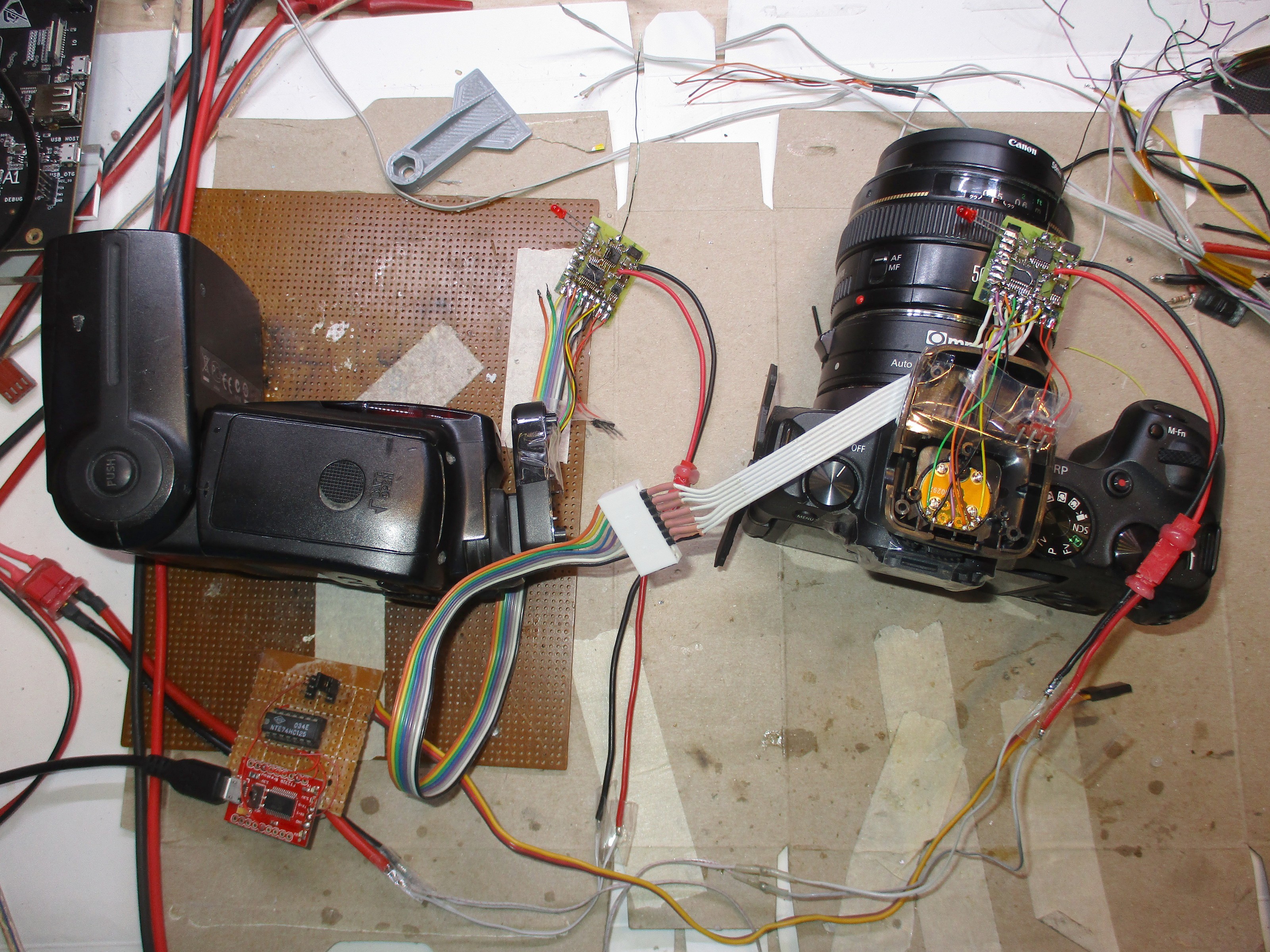
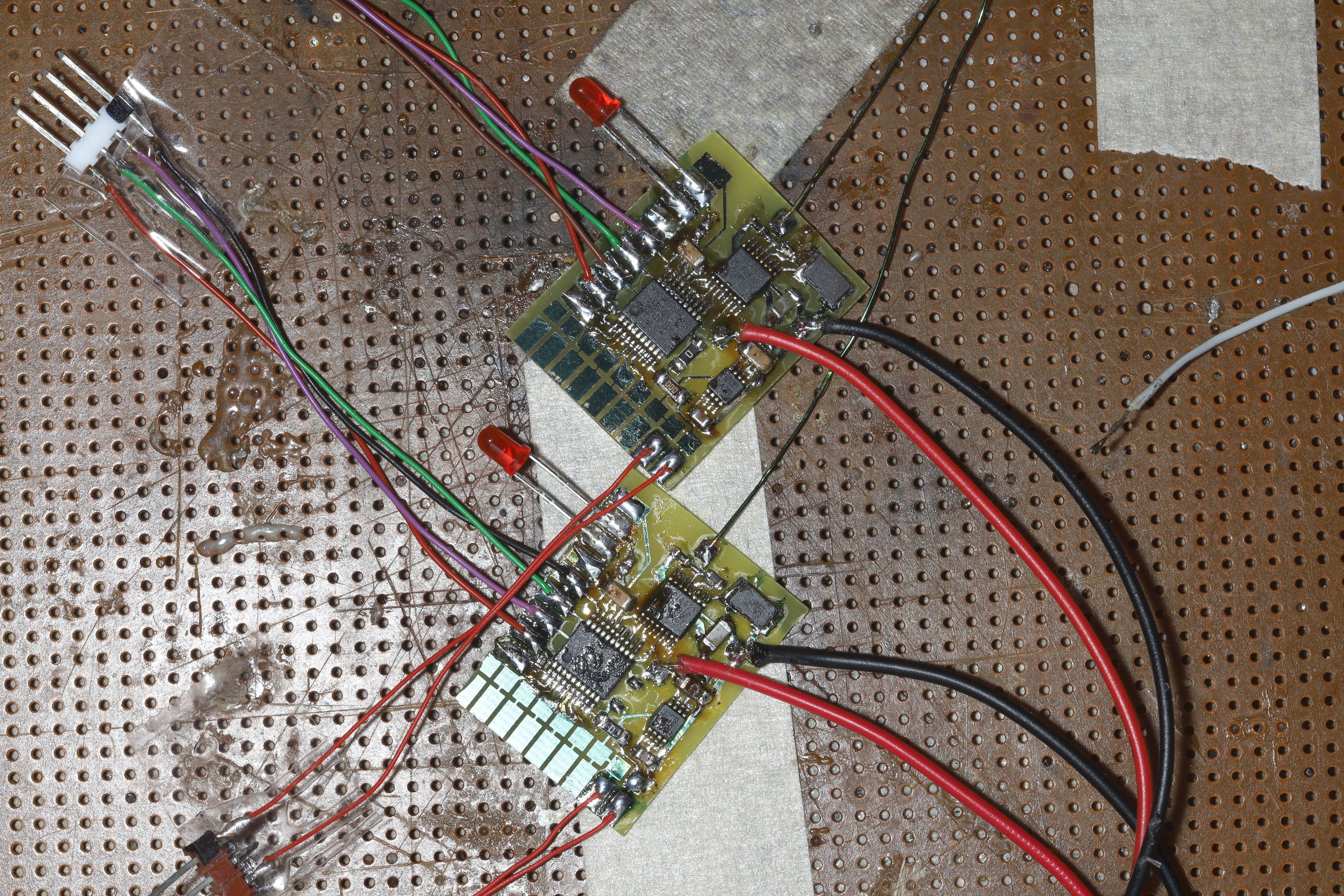
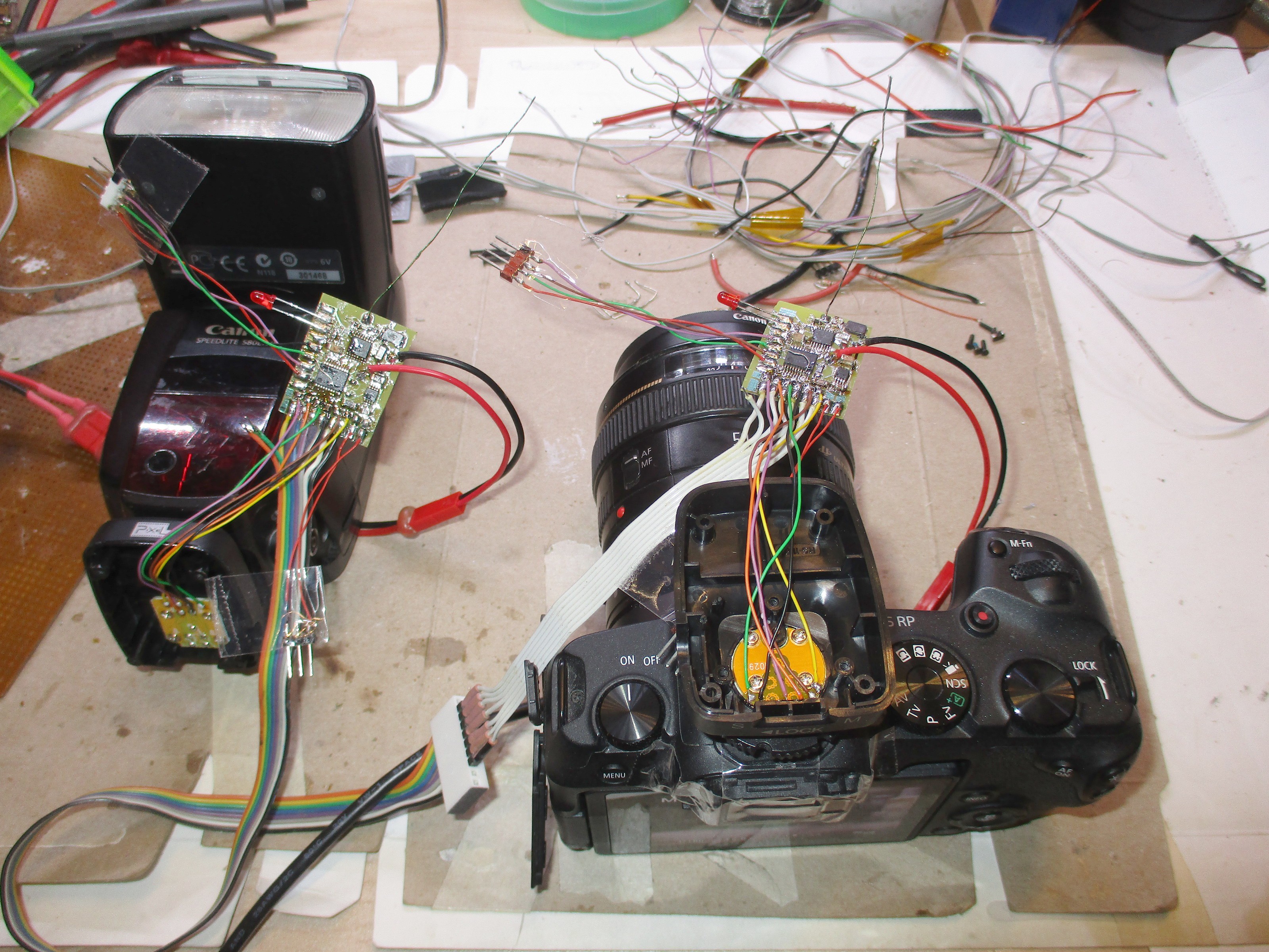
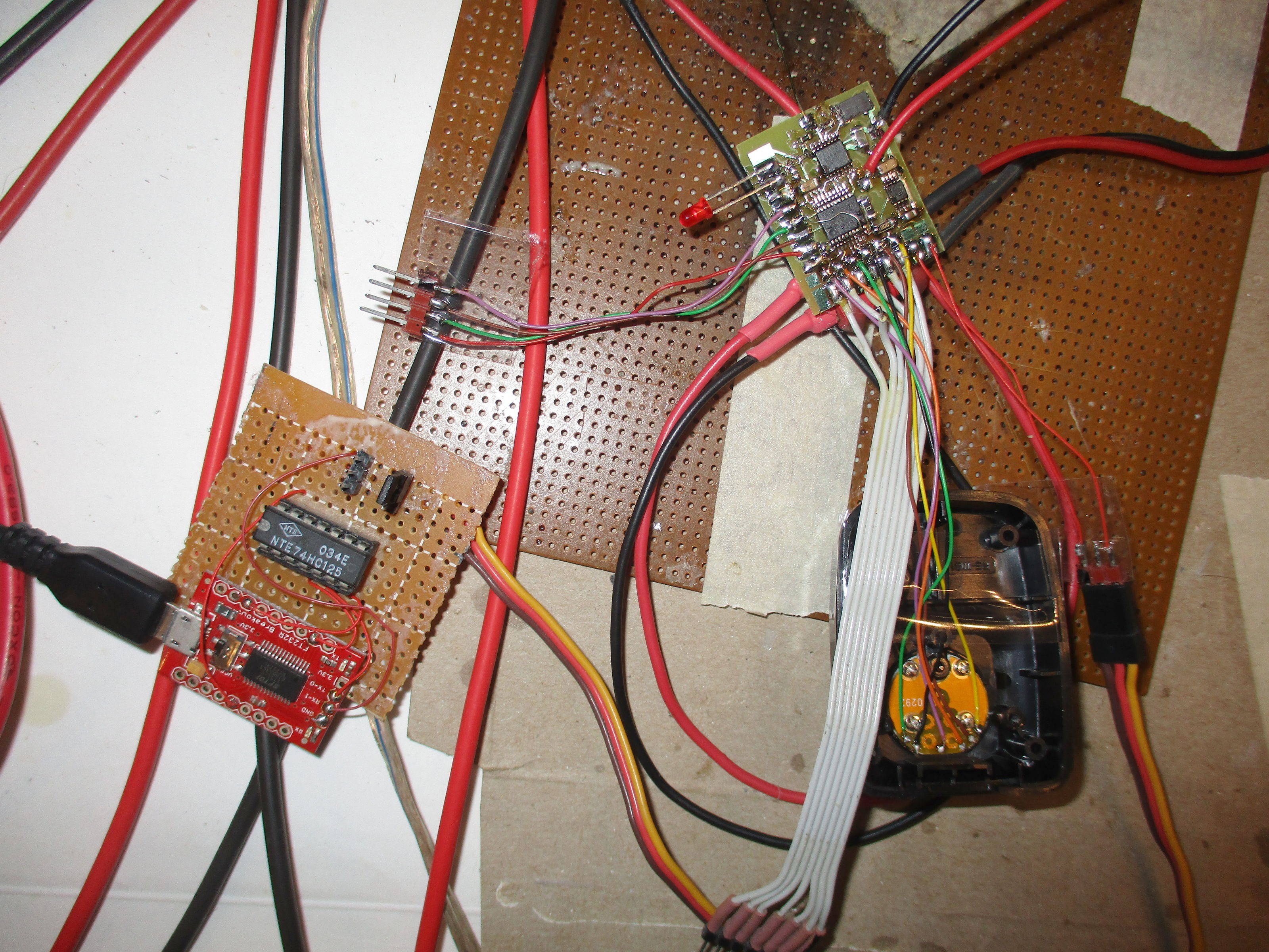
ETTL protocol with the EOS RP & 580 EX II
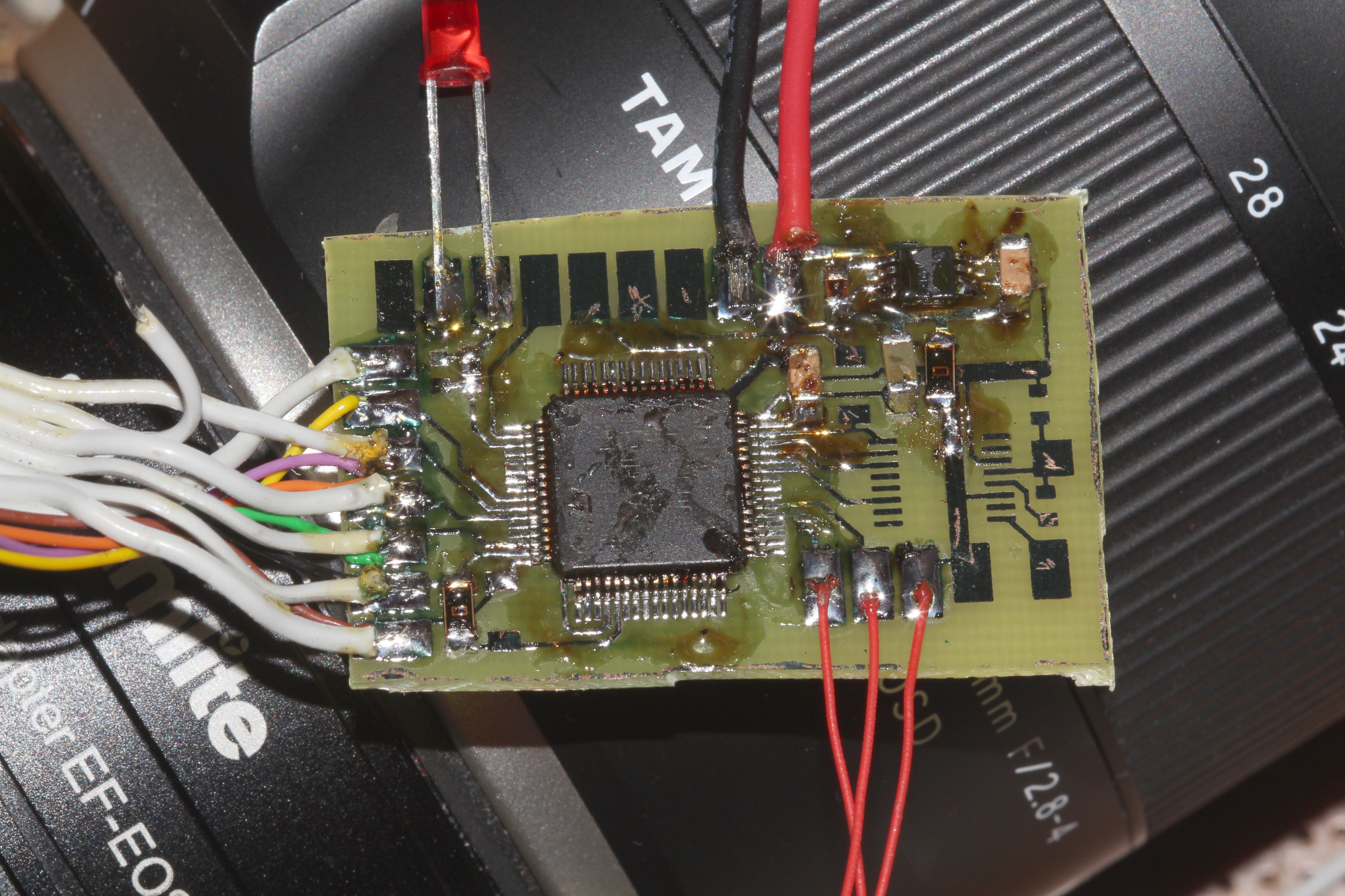
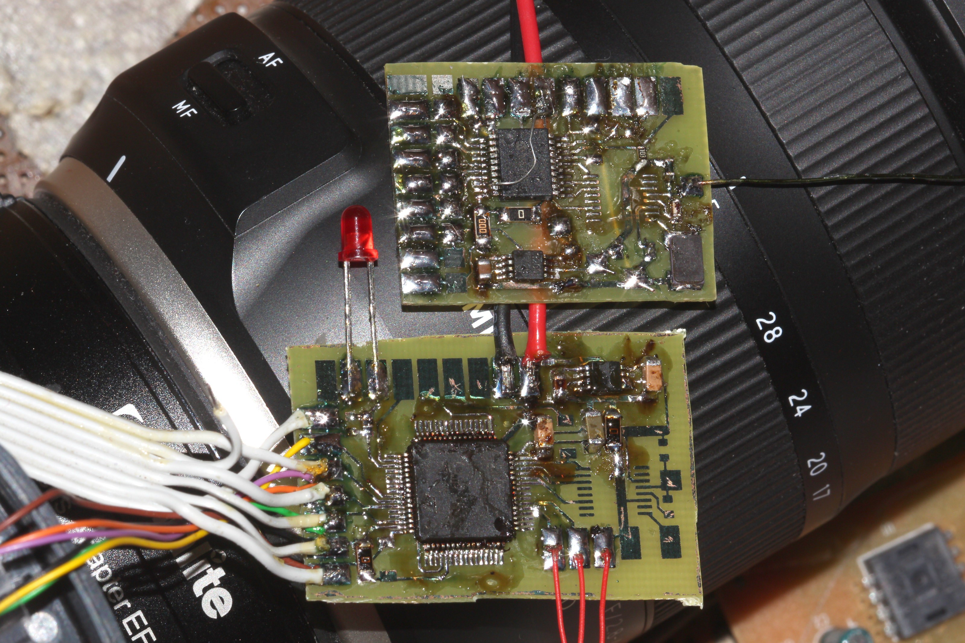
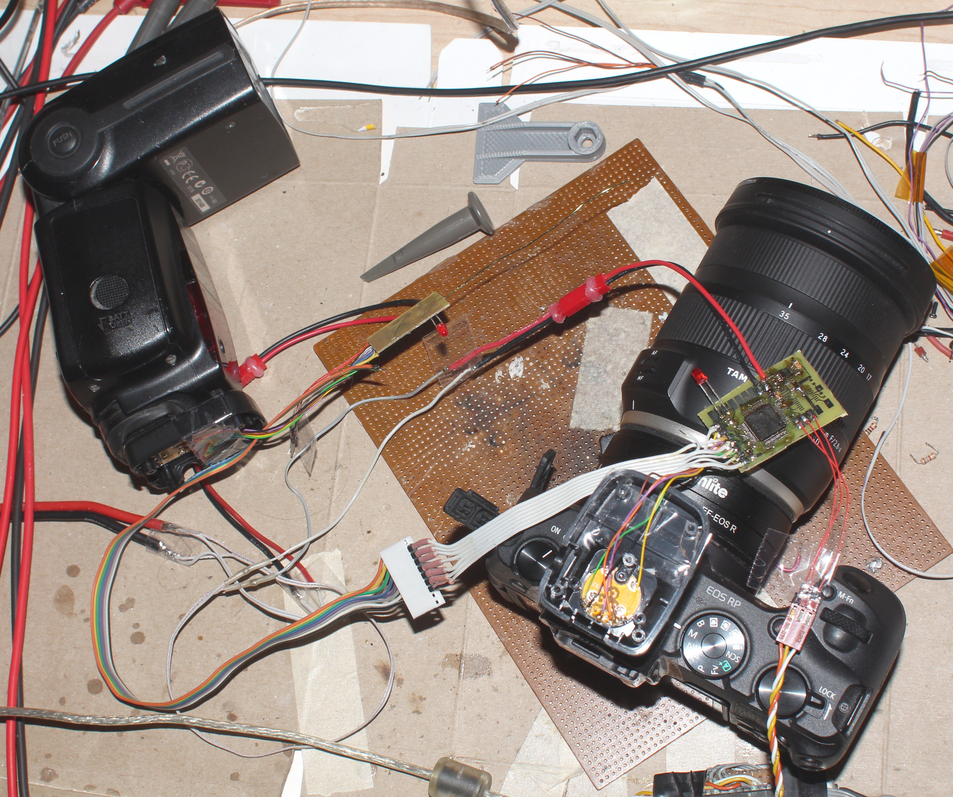
12/08/2022 at 05:30 • 0 comments![]()
![]()
![]()
The STM32 board was just a hair bigger than the PIC, but the biggest pieces are still the power switch, channel button, & battery. The plan is just to print an L enclosure which scotch tapes around the hot shoe & sticks up. The antenna will stick vertically in a plastic tube. The original hot shoe farsteners won't be used. The flash enclosure will be a horizontal board.
The STM32 at 168Mhz can sample all 3 ADCs at 2Mhz. X can be sampled digitally. ID requires analog sampling, so it has to sample CLK full time & either sample ID if CLK is high or D1 (from flash) if CLK is low. D1 is only sampled for protocol sniffing. There's no plan to send any data from the flash to the camera via a bidirectional radio.
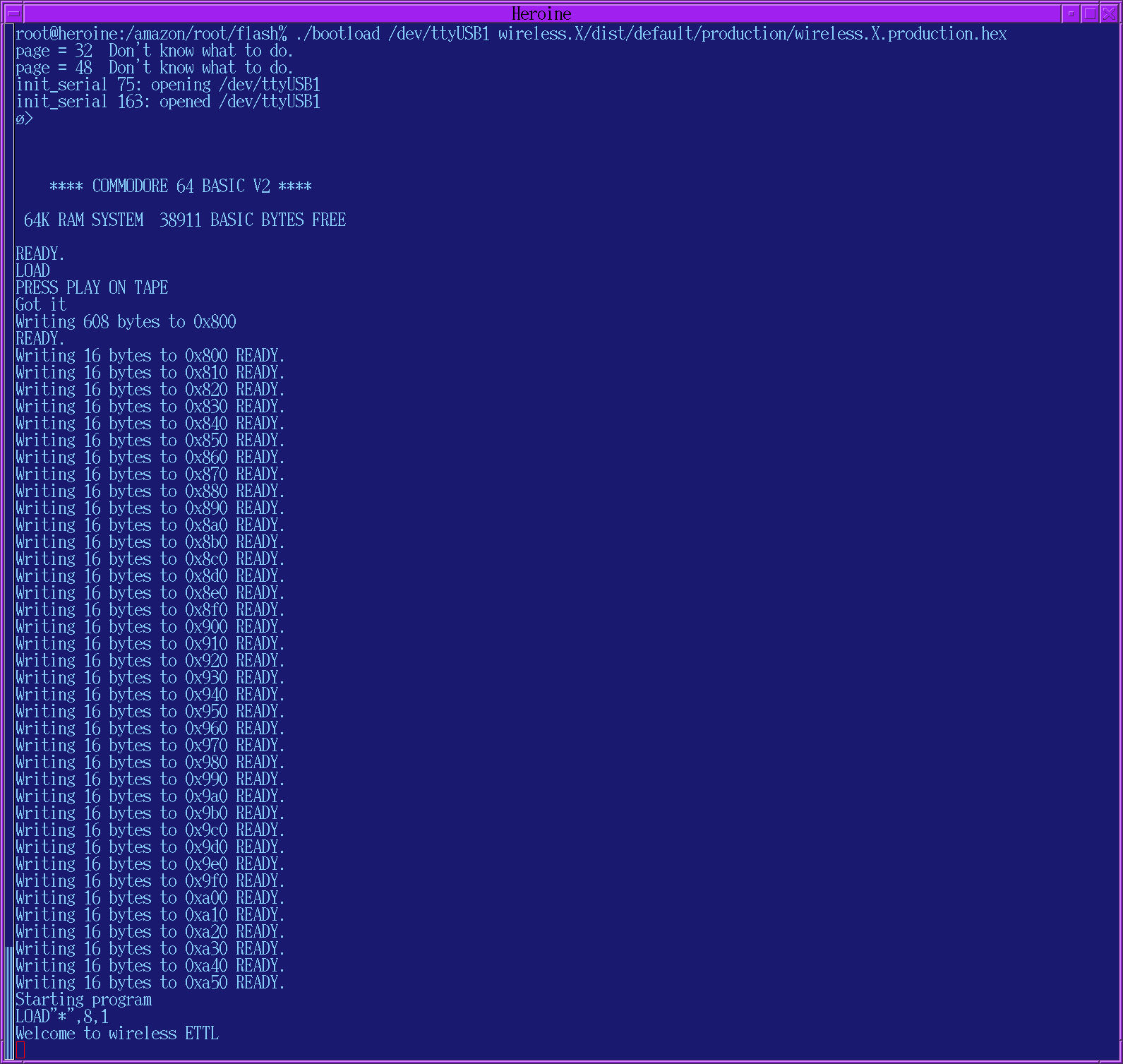
Fortunately, the data comes in slowly enough to print. Sadly, the decoded data during metering is gibberish & matches very little of http://staff.www.ltu.se/~joborg/ettl/.
B5 is a start code. Then the rest departs.
Welcome to wireless ETTL
FROM FLASH        TO FLASH
ff                ff
8e                b5
de                4c
8e                ff
8e                b5
de                4c
8e                e5
0d                ff
8e                a9
91                25
8e                a1
2b                f8
2b                a5
00                2c
8e                b9
00                80
8e                bd
aa                00
59                1c
00                99
ff                fb
02                ff
8e                f9
75                ff
8e                f7
7b                ff
8e                b3
00                12
00                46
00                2f
00                f5
57                ff
49                ff
5c                ff
0f                ff
00                be
8e                14
8e                bb
00                48
00                ff
8e                e6
3f                ff
10                ff
00                ff
8e                b7
8e                38
8e                b8
8e                6d
8e                b4
8e                1d
The object of the game is replaying the conversation rather than knowing what any of the data means, so the trick is detecting repeating patterns, tracking just the differences. It can print time differences between bytes.
It emits nothing when powering up the cam before the flash.
It emits a single packet when powering up the flash before the cam:
Welcome to wireless ETTL
FROM FLASH/TO FLASH/uS DIFFERENCE/PACKET OFFSET
ff    ff    3189193    0
8e    b5    117    1
de    4c    111    2
8e    ff    116    3
8e    b5    116    4
de    4c    111    5
8e    e5    75    6
0d    ff    117    7
8e    a9    115    8
91    25    117    9
8e    a1    83    10
2b    f8    154    11
2b    a5    84    12
00    2c    116    13
8e    b9    88    14
00    80    117    15
8e    bd    70    16
aa    00    116    17
59    1c    69    18
00    99    74    19
ff    fb    112    20
02    ff    116    21
8e    f9    116    22
55    ff    117    23
8e    f7    116    24
7b    ff    112    25
8e    b3    116    26
00    12    158    27
00    46    84    28
00    2f    74    29
00    f5    74    30
57    ff    116    31
49    ff    69    32
5c    ff    71    33
0f    ff    74    34
00    be    70    35
8e    14    120    36
8e    bb    71    37
00    48    116    38
00    ff    69    39
8e    e6    117    40
3f    ff    121    41
10    ff    88    42
00    ff    83    43
8e    b7    117    44
8e    38    112    45
8e    b8    74    46
8e    6d    111    47
8e    b4    69    48
8e    1d    117    49
8e    a8    69    50
91    00    116    51
Tapping the metering button emits a long sequence of packets which automatically times out.
The start of a packet sequence for metering:
Welcome to wireless ETTL
FROM FLASH/TO FLASH/uS DIFFERENCE/PACKET OFFSET
ff    ff    17591745    0
8e    b5    117    1
de    4c    125    2
8e    ff    159    3
8e    b5    115    4
de    4c    112    5
8e    e5    75    6
0d    ff    120    7
8e    a9    116    8
91    25    117    9
8e    a1    84    10
2b    f8    153    11
2b    a5    84    12
00    2c    121    13
8e    b9    88    14
00    80    116    15
8e    bd    69    16
aa    00    131    17
59    1c    69    18
00    99    70    19
ff    fb    111    20
02    ff    117    21
8e    f9    125    22
75    ff    116    23
8e    f7    117    24
7b    ff    125    25
8e    b3    117    26
00    12    157    27
00    46    84    28
00    2f    88    29
00    f5    89    30
57    ff    134    31
49    ff    69    32
5c    ff    69    33
0f    ff    84    34
00    be    70    35
8e    14    121    36
8e    bb    79    37
00    48    116    38
00    ff    70    39
8e    e6    129    40
3f    ff    135    41
10    ff    89    42
00    ff    88    43
8e    b7    116    44
8e    38    112    45
8e    b8    88    46
8e    6d    111    47
8e    b4    70    48
8e    1d    112    49
8e    a8    69    50
91    00    131    51
8e    a5    148    52
00    2d    117    53
8e    a5    288    54
01    2c    116    55
8e    ff    47540    0
8e    b5    116    1
de    4c    112    2
8e    e5    75    3
0d    ff    125    4
8e    a9    117    5
91    25    116    6
8e    a1    84    7
2b    f8    153    8
2b    a5    84    9
00    2c    116    10
8e    b9    93    11
00    80    116    12
8e    bd    69    13
18    00    126    14
69    1c    69    15
1e    99    70    16
ff    fb    111    17
02    ff    117    18
8e    f9    125    19
75    ff    116    20
8e    f7    117    21
7b    ff    125    22
8e    b3    116    23
00    12    158    24
00    46    83    25
00    2f    74    26
00    f5    75    27
57    ff    121    28
49    ff    70    29
5c    ff    70    30
0f    ff    83    31
00    be    70    32
8e    14    121    33
8e    bb    79    34
00    48    116    35
00    ff    70    36
8e    e6    130    37
3f    ff    130    38
10    ff    93    39
00    ff    88    40
8e    b7    117    41
8e    38    112    42
8e    b8    83    43
8e    6d    111    44
8e    b4    71    45
8e    1d    111    46
8e    a8    70    47
91    00    116    48
8e    a5    149    49
00    2d    116    50
8e    a5    335    51
01    2c    116    52
8e    ff    48556    0
8e    b5    121    1
de    4c    111    2
8e    e5    75    3
0d    ff    129    4
8e    a9    117    5
91    25    121    6
8e    a1    83    7
2b    f8    153    8
2b    a5    83    9
00    2c    117    10
8e    b9    83    11
00    80    117    12
8e    bd    69    13
18    00    130    14
69    1c    70    15
1c    99    69    16
ff    fb    111    17
02    ff    116    18
8e    f9    125    19
55    ff    116    20
8e    f7    117    21
7b    ff    125    22
8e    b3    116    23
00    12    158    24
00    46    84    25
00    2f    74    26
00    f5    74    27
57    ff    121    28
49    ff    70    29
5c    ff    69    30
0f    ff    83    31
00    be    70    32
8e    14    121    33
8e    bb    79    34
00    48    116    35
00    ff    70    36
8e    e6    125    37
3f    ff    121    38
10    ff    84    39
00    ff    84    40
8e    b7    115    41
8e    38    111    42
8e    b8    75    43
8e    6d    125    44
8e    b4    70    45
8e    1d    111    46
8e    a8    70    47
91    00    116    48
8e    a5    1889    49
00    2d    121    50
8e    a5    288    51
01    2c    116    52
8e    ff    46831    0
The timing is pretty consistent, so we can strip it down to packets.
The camera powerup is 52 bytes:
FROM FLASH/TO FLASH
7f/7f 8e/b5 de/4c 8e/ff 8e/b5 de/4c 8e/e5 0d/ff
8e/a9 91/25 8e/a1 2b/f8 2b/a5 00/2c 8e/b9 00/80
8e/bd aa/00 59/23 00/99 ff/fb 02/ff 8e/f9 55/ff
8e/f7 7b/ff 8e/b3 00/12 00/46 00/2f 00/f5 57/ff
49/ff 5c/ff 0f/ff 00/be 8e/14 8e/bb 00/48 00/ff
8e/e6 3f/ff 10/ff 00/ff 8e/b7 8e/38 8e/b8 8e/6d
8e/b4 8e/1d 8e/a8 91/00
Metering starts with a 56 byte packet:
FROM FLASH/TO FLASH
7f/7f 8e/b5 de/4c 8e/ff 8e/b5 de/4c 8e/e5 0d/ff
8e/a9 91/25 8e/a1 2b/f8 2b/a5 00/2c 8e/b9 00/80
8e/bd aa/00 59/23 00/99 ff/fb 02/ff 8e/f9 55/ff
8e/f7 7b/ff 8e/b3 00/12 00/46 00/2f 00/f5 57/ff
49/ff 5c/ff 0f/ff 00/be 8e/14 8e/bb 00/48 00/ff
8e/e6 3f/ff 10/ff 00/ff 8e/b7 8e/38 8e/b8 8e/6d
8e/b4 8e/1d 8e/a8 91/00 8e/a5 00/2d 8e/a5 01/2c
then a repeating 53 byte packet until it times out.
FROM FLASH/TO FLASH
8e/ff 8e/b5 de/4c 8e/e5 0d/ff 8e/a9 91/25 8e/a1
2b/f8 2b/a5 00/2c 8e/b9 00/80 8e/bd 18/00 69/23
23/99 ff/fb 02/ff 8e/f9 55/ff 8e/f7 7b/ff 8e/b3
00/12 00/46 00/2f 00/f5 57/ff 49/ff 5c/ff 0f/ff
00/be 8e/14 8e/bb 00/48 00/ff 8e/e6 3f/ff 10/ff
00/ff 8e/b7 8e/38 8e/b8 8e/6d 8e/b4 8e/1d 8e/a8
91/00 8e/a5 00/2d 8e/a5 01/2c
The 1st byte is random. It's going to take some logic to figure out what packet to replay. Meter packet #1 seems to be powerup packet + 4 bytes. Meter packet #2 seems to start with 0xb5, 0x4c, 0xe5 instead of 0xb5, 0x4c, 0xff.
When the flash LCD shows the current F stop or the camera LCD shows the flash icon, it's happening during this metering packet sequence. After the sequence ends, the screen widgets go away until you press the metering button again. The next problem is sampling X.
All standard metering packets end with
8e/a5 00/2d
X 0V

X 3.3V
8e/a5 01/2c
It seems triggering the preflash requires the following packet:
8e/ff 8e/b4 8e/1d 8e/f2 c0/ff 8e/ff 8e/b4 8e/03
8e/f2 a0/ff 8e/b0 8e/80 8e/b1 8e/04 8e/b3 00/12
00/46 00/2f 00/b4 8e/23
CLK 0V

CLK 3.3V
(end of preflash packet)
The mane flash comes next with the following packet:
ff/ff 8e/b3 00/32 00/46 00/2f 00/f8 3a/ff
8e/bb 00/48 00/ff 8e/b7 8e/38 8e/b8 8e/6d 8e/b0
8e/88 8e/b4 8e/1d 8e/f2 c0/ff 8e/b3 00/36 00/46
00/2f 00/b4 8e/3d

CLK 0V
X 0V
X 3.3V
CLK 3.3V

7f/b4 8e/1d 8e/b3 00/12 00/46 00/2f 00/fc 88/ff
c0/ff 1a/ff 2a/ff 85/ff 78/ff
(end of mane flash packet)

8e/ff 8e/b5 de/4c 8e/e5 0d/ff 8e/a9 91/25 8e/a1
2b/f8 2b/a5 00/2c 8e/b9 00/80 8e/bd 18/00 69/23
23/99 ff/fb 02/ff 8e/f9 55/ff 8e/f7 7b/ff 8e/b3
00/12 00/46 00/2f 00/f5 57/ff 49/ff 5c/ff 0f/ff
00/be 8e/14 8e/bb 00/48 00/ff 8e/e6 3f/ff 10/ff
00/ff 8e/b7 8e/38 8e/b8 8e/6d 8e/b4 8e/1d 8e/a8
91/00
(metering packet without 8e/a5 00/2d 8e/a5 01/2c)
Standard metering packets ending with
8e/a5 00/2d
X 0V

X 3.3V
8e/a5 01/2c
follow until the timeout. If multiple flashes fire in succession, the last 91/00 goes straight into the next preflash packet.
ID is 1.4V through all of the metering, exposures & 0V otherwise.
The next step is tracking down what changes with different flash & camera settings, especially the focal length, the flash power setting.
-
Death of the PIC
12/06/2022 at 00:51 • 0 commentsSo 1 of the boards had a short between X & ID that managed to scrape by the initial day of testing. With it cleared, the flash worked perfectly with the signals in bypass mode. The flash interface accepted button presses & the camera didn't lock up. Running the boards on 3.3V or 5V made no difference so hope resumed for a digital 3.3V interface.
Anyways, the decision was made to try to capture data. Data moves at 100kbaud but CLK toggles at 200khz. There's no rising edge detection on the PIC comparator. It fires an interrupt for every change. The comparator seems to get behind. Trying to do it in C was too slow.
![]()
Rising edges were pictured by a toggling of 1. Polling was faster than interrupts, but still too slow to do anything. It would have to read comparator 2 to read a data pin & then write a data pin. Maybe a tight assembly loop could catch a single byte at a time before processing the data in the 50us between bytes. It couldn't print anything because a single UART byte takes 100us. The trick is catching the start of the byte. It would have to spend its life in an assembly loop polling all 5 signals & only do any processing after the 8th bit.
The other question is if the camera & flash detect the presence of each other by a non zero voltage on the data pins, that's why digital 0 is 2V. It really needs an STM32 with 2 DACs for CLK, data out & 2 ADCs for CLK, data in. Analog capture of X, ID, & data out is only needed for debugging. X & ID can go to 0V. There could be a debugging mode with taps of all the signals going to ADCs. The DACs avoid the need for op amps. This bigger board would go vertically on the hot shoe.
The beloved single wire bootloader goes in the scrap heap.
-
Busted
12/05/2022 at 05:56 • 0 comments![]()
Definitely cleaner without the programming headers.
Sadly, the bypass circuit doesn't work reliably. This wasn't previously tested very thoroughly. The camera is prone to locking up, manely after the flash fires. The flash user interface doesn't detect any button presses, especially exposure compensation. It may be the voltages really have to go to 5V. The circuit is going to limit them to 3.3V.
It would require a 5V micro with resistor ladders to create the analog voltages, op amps for buffering, 1Mhz ADC for reading the analog voltages. It's on the scale of building a confuser from scratch. There are animals who build confusers from scratch. Just not sure it's worth eliminating a cable.
It busts another idea about converting a vintage flash to ETTL.
There needs to be a test board to see if all the analog voltages or just 5V are required. It could be a bag of comparators.
Noted a minimum 50us gap between bytes for framing. The flash always shows the current F stop value outside of metering mode so it doesn't just need preflash & flash triggers. CLK goes to ground when the camera is 1st powered up, in addition to the other cases described.
A fully manual, wireless flash would be easy to cobble together, but that's not what lions want.
The top of the line Godox increased from $180 to $200. Maybe a cable isn't so bad. The wireless idea was manely about the cable wearing out & convenience, but it seems to be not very compelling. A radio is a big failure point.
-
Single wire bootloader
11/30/2022 at 05:13 • 0 comments![]()
There was thus a transmit & receive board with test leads attached. The transmitter is distinguished by an extra jumper resistor. The only bodges were A0 not having any output mode & A1 not having a pullup. It was finally time to sacrifice the extension cord.
![]()
Careful mapping of the pins
![]()
![]()
allowed resoldering to the development boards
The mane problem with sniffing the flash signals is both boards have to be powered on.
There was a real desire for a bootloader this time, with so many cables being required. The mane problems are these parts being end of life, the interrupt vector, & only 1 serial line. The last bootloader a lion wrote for a 1 off project was for the mighty STM32, back when those just came out & were in long term production. The 1st bootloader a lion wrote for a PIC was for the PIC18F458. That one used the programming pins.
It would have to use the serial port, but the radio boards all short the TX & RX pins. To receive & transmit on a single wire, the FTDI needs a tristate buffer for the TX, controlled by the DTS pin.
The mane problem with a single wire UART is we don't know when the FTDI is finished writing the last byte. The kernel is happy to toggle the DTS pin before the TX pin is finished writing. The best option is to read back every byte written, since the RX pin is always on. Now the problem is knowing when the FTDI has read back the last byte written so the PIC knows when to transmit. The best the PIC can do is delay, which makes a single wire bootloader very slow.
XC8 has a strange bug where it skips the memory from 0x00d0 to 0x300. This only goes away if
--codeoffset=0x800
After 2 solid days, the lion kingdom's 2nd PIC bootloader in 20 years came alive.
![]()
![]()
It's a grotesque waste of memory for a bootloader to print so much text, but it was about making supporting this obsolete part less miserable.
-
Odd logic voltages
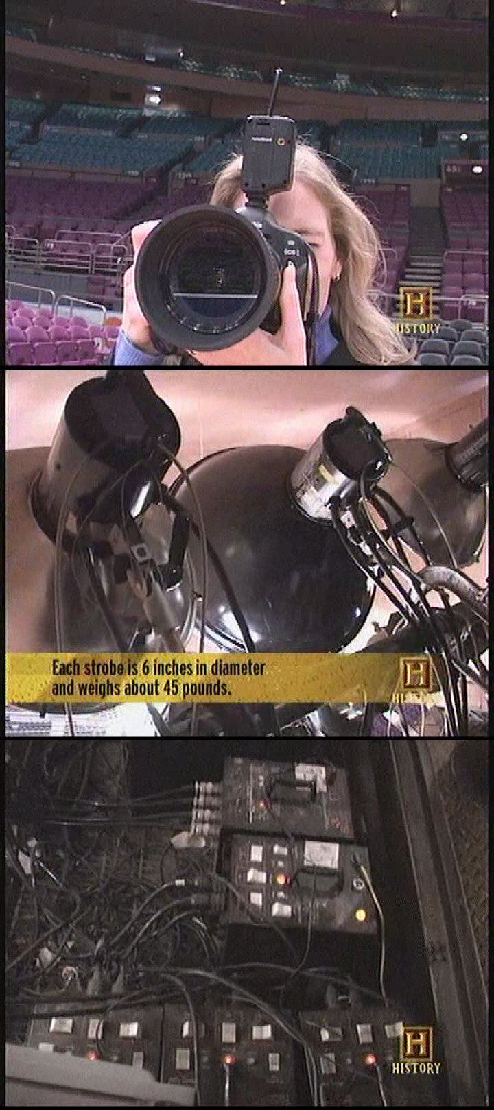
11/14/2022 at 02:49 • 0 commentsMore or less still a sleeper project because the cabled extension cord still works. For years, lions thought everyone else had a wireless flash & the cable was stupid. That might have come from a video about the house flash in a stadium.
![]()
Those were actually fixed power.
Later experience showed a wireless ETTL flash is really expensive & hard to achieve with vintage gear. Wireless ETTL was definitely not supported in any lion cameras as previously thought. Even the EOS RP doesn't support wireless ETTL. Everyone else was really using cables or refinancing. That definitely deprioritized the idea.
The lion kingdom doesn't really use ETTL. It shoots at 1/100s TTL at most. The flash just has to hit a .01ms window.
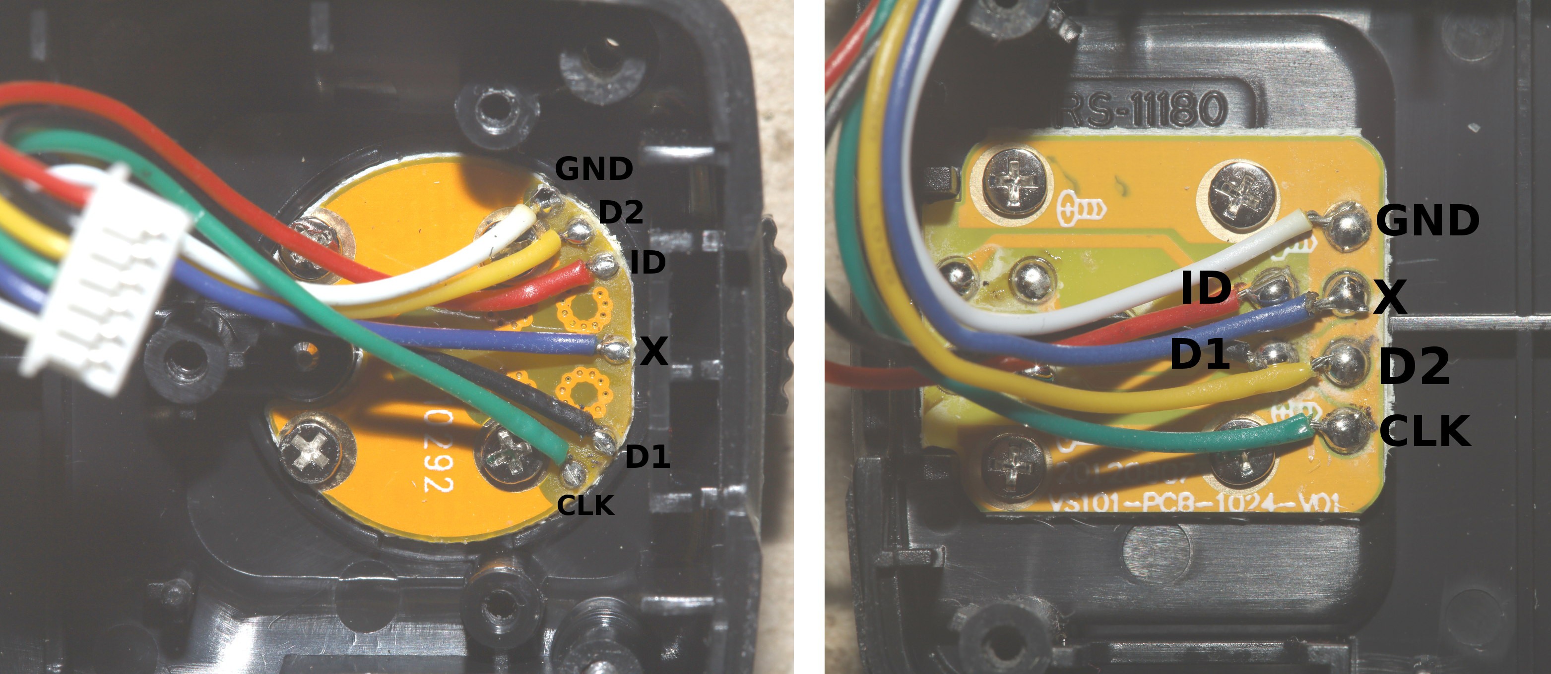
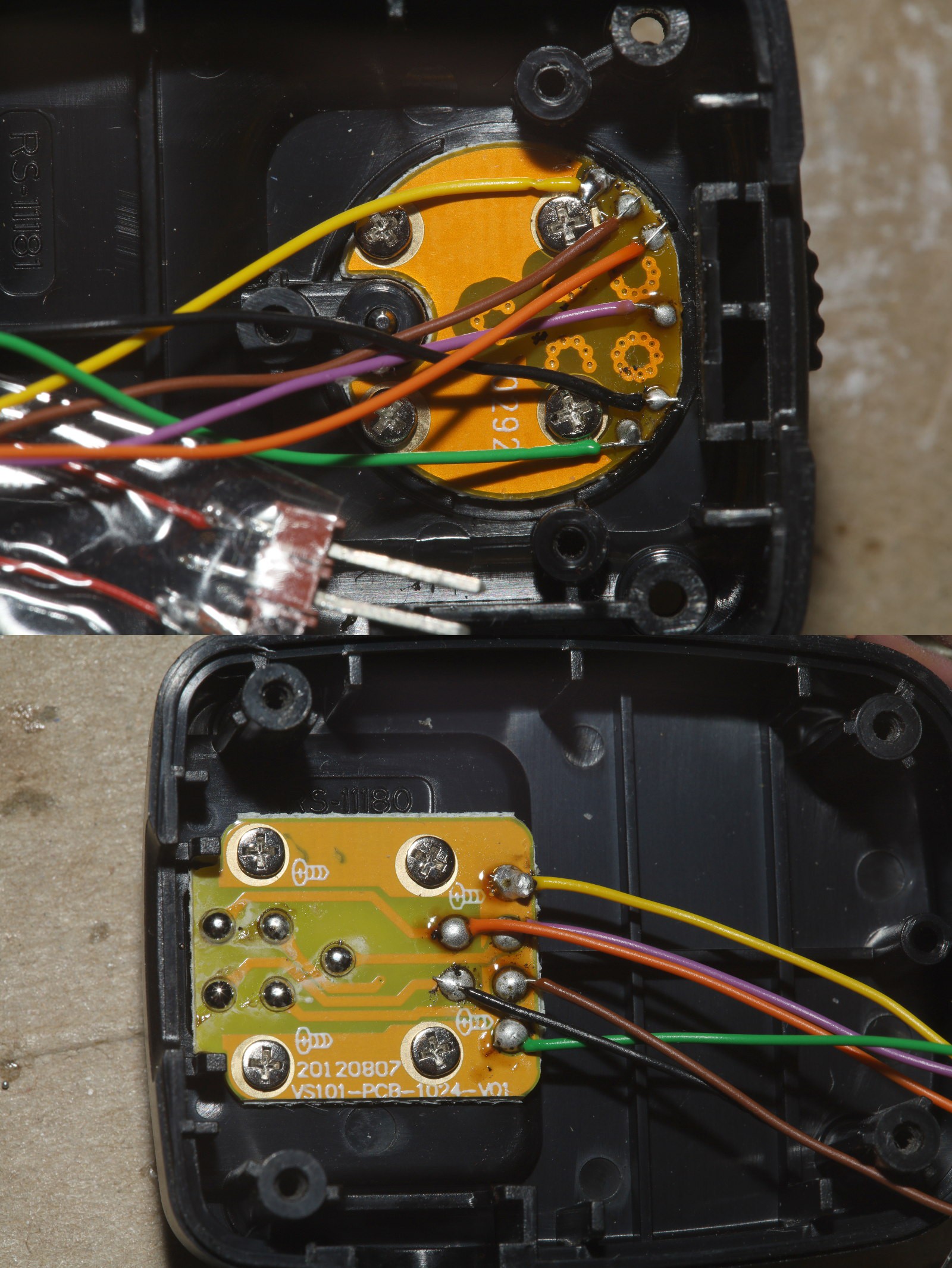
A test of the EOS RP showed the odd voltages from 30 years ago still being used.
http://staff.www.ltu.se/~joborg/ettl/
X -> 0-5V
CLK -> 2-5V
MISO -> 2-3.3V
MOSI -> 2-3.3V
ID -> 1.2-3.3V
So reading the signals requires comparators with triggers at 2.7V. The 18F14K50 has 2 comparators, 3 useful comparator inputs & a DAC. The 4th comparator input in the datasheet can't use the DAC. The 3 inputs can go to CLK, MISO, MOSI. The CLK can be always connected, fire an interrupt, which then causes it to poll the data inputs with the other comparator. The less time critical ID pin can be an ADC input.
Creating the signals should be possible with just GPIOs. CLK, MISO, MOSI fire at 104khz. X is an open drain. The others are active.
A bit banged SPI reader has 153 instructions per bit with the 18F14K50 at a maximum 32Mhz, but there are framing gaps between bytes to do processing.
A 1 way protocol is highly appealing. The only 2 wire commands are metering & triggering. The rest are queries, power setting, zoom setting which the transmitter can emulate. The general observation is the camera constantly sends commands to the flash in the meter step & there's not enough time between meter & trigger for an ACK. If the flash is always receiving, there's no way to debug it, so that's a jumper resistor for the TX pin.
The next item is selecting the channel. The idea is to have 1 momentary button. Tap it to see the current channel. Press & hold to cycle through the channels. The LED would blink some binary pattern to indicate the channel, long would be 1, short would be 0. long short long short would be 6. Short short short long would be 1. It would only be slightly worse than a keychain cam interface. Viewing it in a video editor might help. In practical use, the user would only match the pattern rather than try to count in binary.
-
Planning
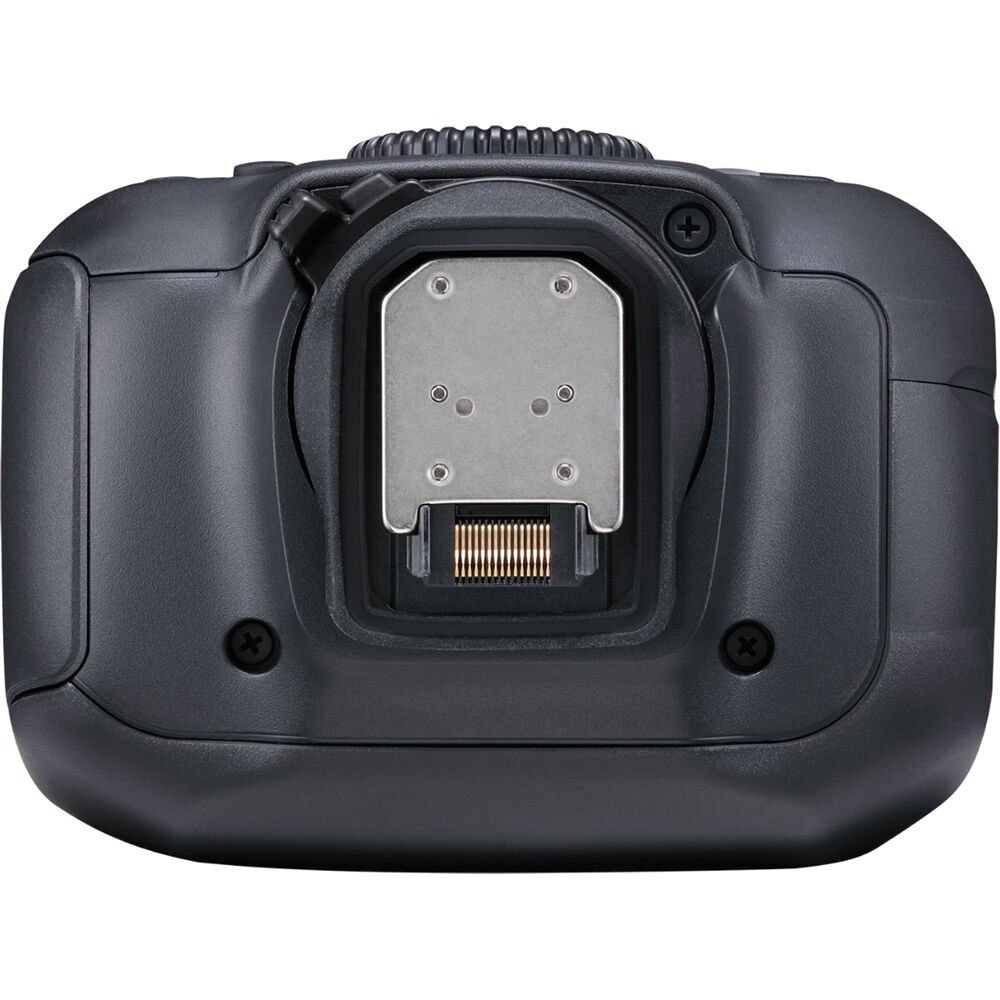
11/12/2022 at 23:49 • 0 commentsCanon abandoned its 5 pin hot shoe of 100 years for a new fine pitch connector.
![]()
But hope springs eternal for lions & we're sticking with the vintage connector.
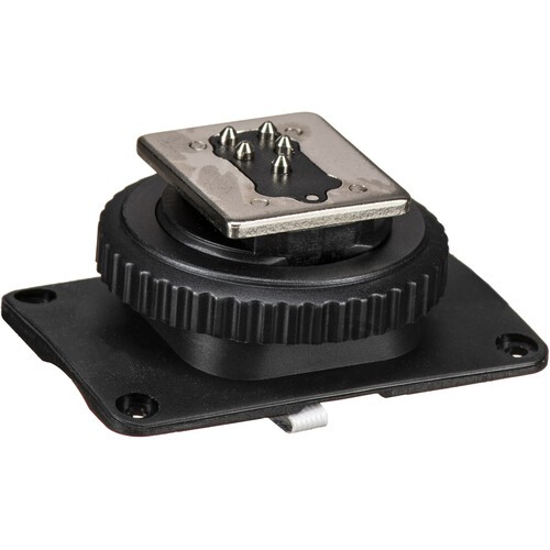
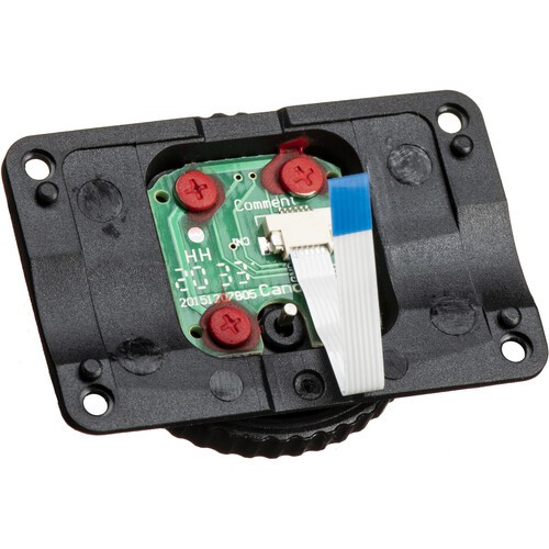
There are a few options for obtaining a bare hot shoe connector pair. The flash side is sold on in its own. This one has an evil FPC connector but is $15:
https://www.bhphotovideo.com/c/product/1609893-REG/godox_v350chotshoe_hot_shoe_for_v350c.html/
![]()
![]()
The same thing for $20:
https://www.amazon.com/GODOX-V860III-C-Replacement-Hotshoe-Mounting/dp/B0BGS5CVHL
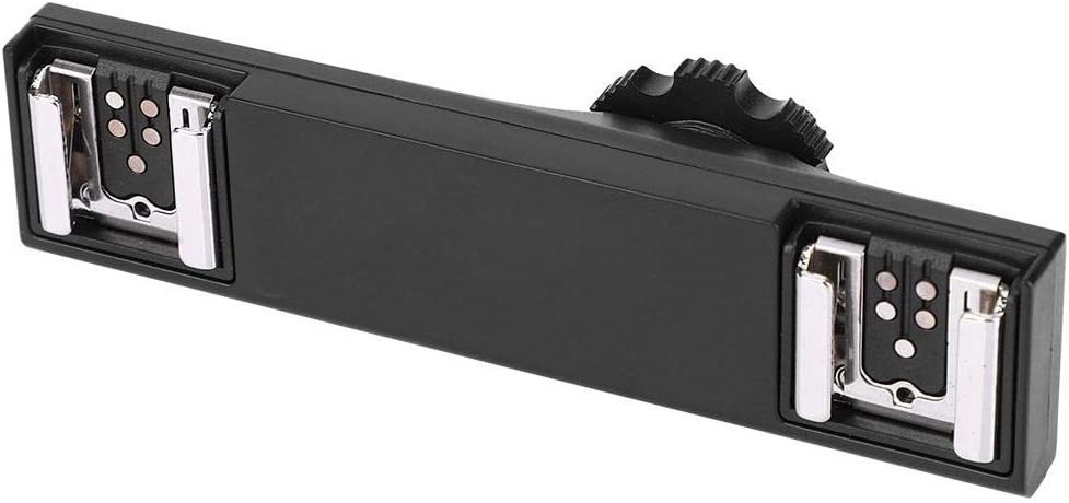
A $19 hot shoe splitter has 2 camera sides & 1 flash side. It would take some scavenging to extract the connectors & it might not be as durable as the alternatives:
https://www.amazon.com/Tangxi-Splitter-Extension-Bracket-Camcorder/dp/B07Y3DMHLR/
![]()
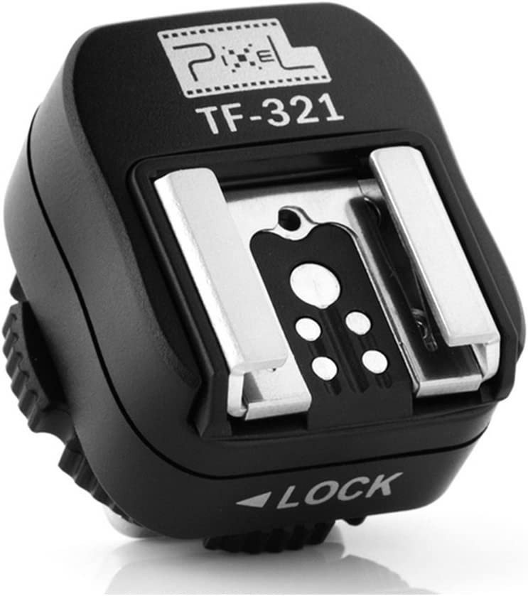
The leading candidate is the $22 Pixel deal. This is going to have fine pitch connectors on the inside. It has an easily separable clamshell:
https://www.amazon.com/Pixel-Flash-Adapter-Extra-Flashguns/dp/B00554PCDG/
![]()
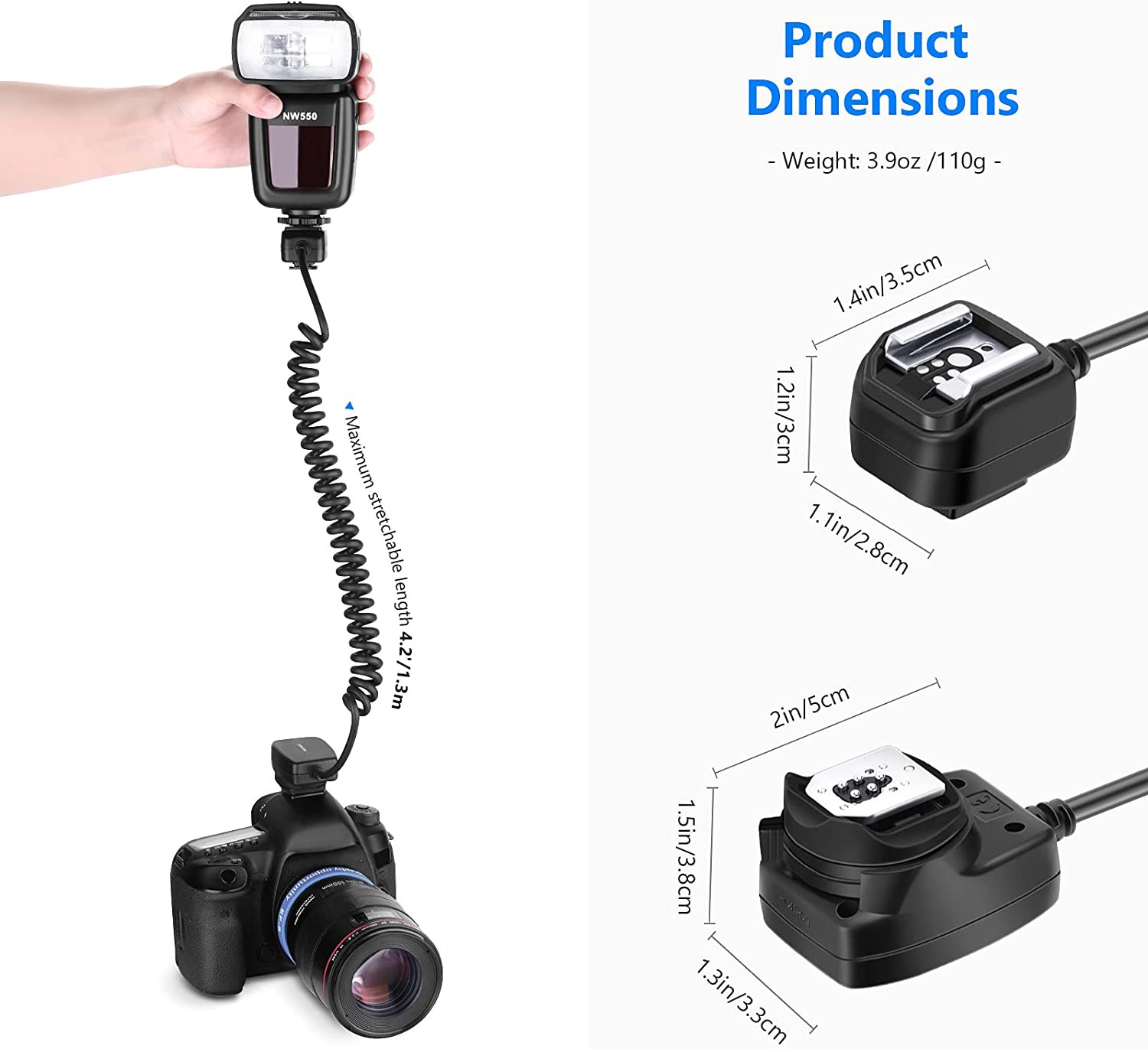
Finally, there's the $25 off camera extension cord lions already have:
https://www.amazon.com/Neewer-Camera-Flash-Speedlite-Canon/dp/B00YUAMMU2
![]()
It's not affordable at the current price. The camera side doesn't have an extra hotshoe as the Dazne Keibe had. The cable would be discarded. It's bulkier than the Pixel.
Building a wireless flash from scratch
Another option is building a wireless flash from scratch & just investing in a $15 flash side hot shoe. The lion kingdom's workhorse 580EX-II is 15 years old & there's probably never going to be another Canon flash. They've all tracked inflation to infinity. The non TTL ones are useless.
The 580EX-II was the best of the best for its time. It has a lot of IR LEDs & photo sensors for non TTL cameras & film cameras. The IR leds were focusing aids before the days of phase autofocus. They only work when they want to work. It uses bulky AA's instead of lipo's. It doesn't have a functional preview mode. The preview mode fires when it wants to fire. The useful bits are the variable focal length, the tilt, the exposure compensation, & the external power.
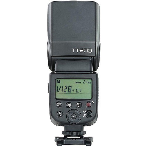
For a bare flash platform, there's the $50 Godox line:
https://www.bhphotovideo.com/c/product/1341884-REG/godox_tt600_camera_speedlite.html/
![]()
Fully manual, but it has zoom, tilt, & the same external power connector as the Canon. The mane problem is it can't be controlled by passing through the ETTL commands. It has no exposure compensation interface. The +0.7 on this display is the fraction part of the manual power setting. It couldn't be mounted on the camera after conversion to wireless. It would have to be just wireless.
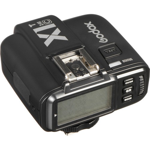
It has a bulky $46 transmitter which controls zoom, power & uses the flash's built in receiver.
https://www.bhphotovideo.com/c/product/1341964-REG/godox_x1t_c_ttl_remote_controller.html/
![]()
But once again, it can't accept ETTL commands. Feeding ETTL commands to the transmitter would be as difficult as feeding the flash.
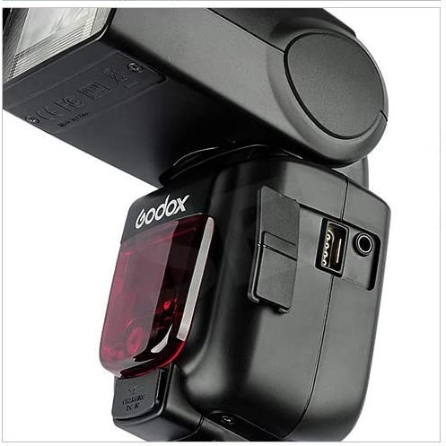
It has a 4 pin control port for an older wireless receiver that might be easier to use.
![]()
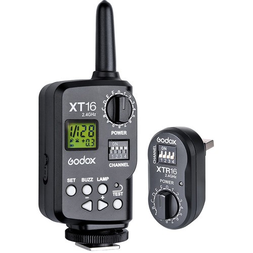
It seems to be intended for the $40 XT-16 radio set.
https://www.bhphotovideo.com/c/product/1341957-REG/godox_xt_16_wireless_radio_controlled_flash.html
![]()
This controls power but not zoom.
None of the wireless transmitters have an exposure compensation interface. That would take a completely separate panel. Using a cheap flash would require completely gutting it, replacing the control panel, removing the focusing aid, removing the batteries, controlling the zoom servo, creating analog signals to control the trigger & power as was done with the 244T. At least all the stuff that didn't work on the 580EX-II could be fixed.
Turnkey Canon system
Then of course, there's doing what lions did 15 years ago & throwing money at the problem.
There is no wireless ETTL support in the EOS RP. It can only trigger a wireless flash by firing a wired flash. There's dropping $400 on a top of the line 600EX II-RT & another $200 on Canon's wireless ST-E3-RT transmitter, almost 1 week of rent.
That's what the internet is doing for wireless ETTL support.
https://www.dpreview.com/forums/thread/4488864
There's an aftermarket transmitter for $100.
https://www.bhphotovideo.com/c/product/1434925-REG/yongnuo_yn_e3_rt_ii_speedlite_transmitter.html/
The 600EX II-RT has no wireless abstraction of the hotshoe. It uses its own wireless protocol, the same as how lions would adapt the 580EX II to wireless.
Turnkey Godox system
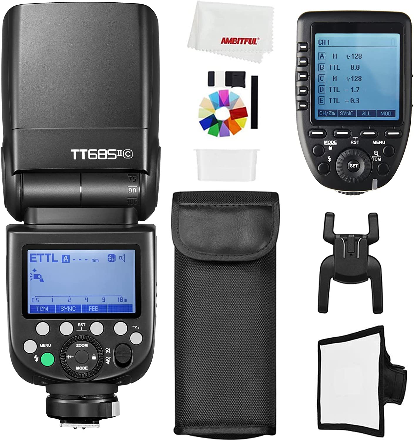
The top of the line Godox is the TT685. A complete Godox TT685 system with ETTL & wireless support is only $180.
https://www.amazon.com/TT685II-C-Speedlite-High-Speed-Wireless-Compatible/dp/B09LCXGTWC
![]()
$180 is pretty close to what lions can afford for wireless, but part of the value in a home made system is being able to prolong the life of the 580EX-II.
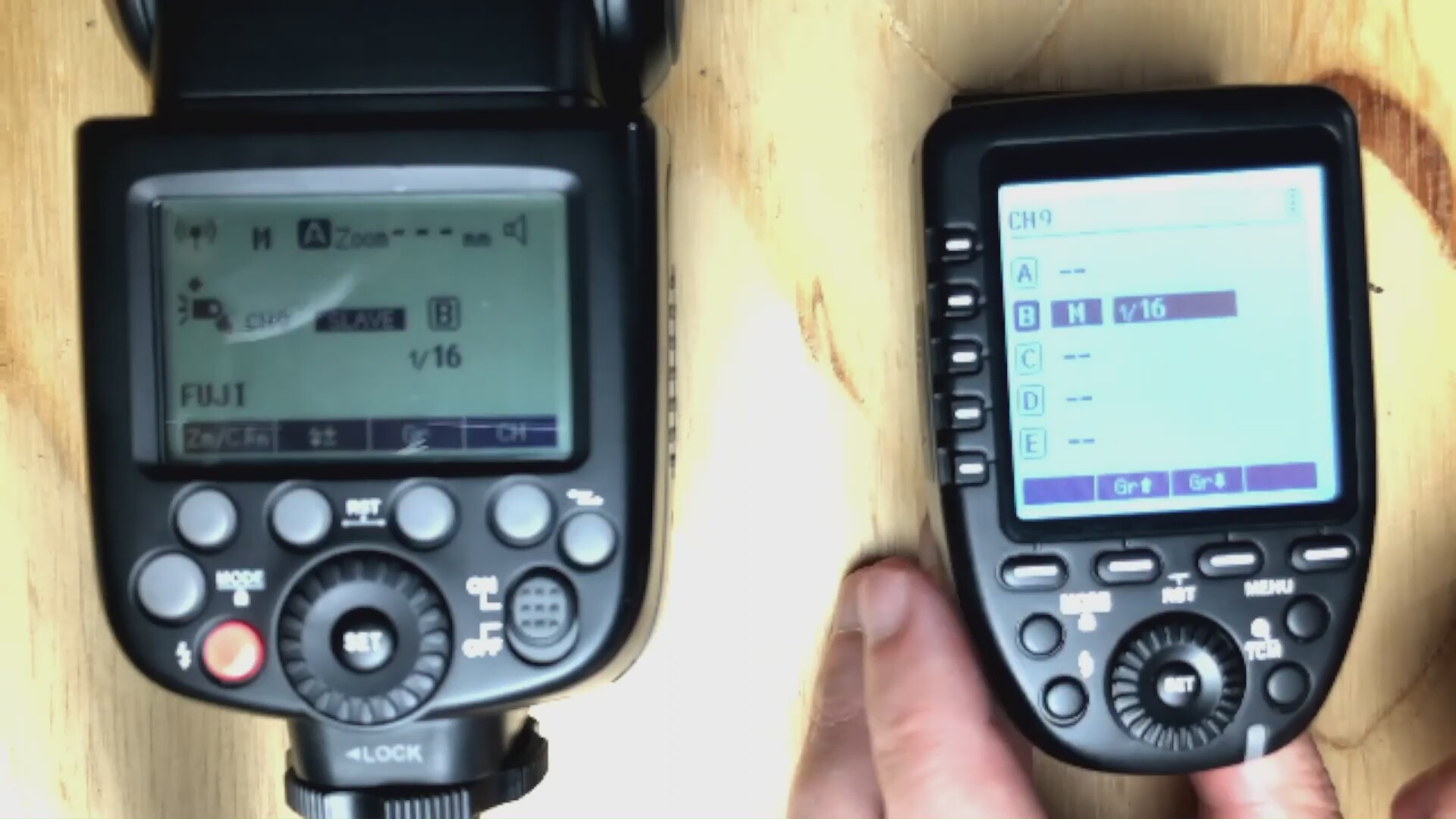
![]()
There's a vijeo showing the transmitter to be as big as the flash body. It does need 2 big AA's.
The godox system eliminates the receiver electronicals, receiver battery, receiver power switch, so the receiver side is slightly more compact & less cumbersome. The mane problem is the size of the transmitter, but it's not a show stopper. It doesn't provide any material value other than saving the time spent developing a system from scratch. The transmitter interface is just gravy.
Radios
The workhorse Si4421 & CC1101 sub Ghz chips are either no longer made or now over $5. It would use the last 2 CC1101 radios in the apartment. The brains would be the last 2 18F14K50's in the apartment. Power would be from lipos with JST's hanging out for charging. The total cost would be just the $25 for the hot shoe adapter, but maybe the cabled system could be recycled. It would be the most compact solution, but not dramatically.
Lions use an off camera flash for almost every single shot. The cabled 580EX-II system is cumbersome & prone to wearing out so maybe the hot shoe adapters from the cable system can be recycled. Lions went 15 years without off camera flash & typically they finish a hard project in 2 weeks. It would entail 2 weeks without off camera flash.
For now, the cabled system works though. It does work on a gimbal but the mane drawback on a gimbal is having to place the flash real close. Longer range on a gimbal might be a big win, but the gimbal has other cables. It might just need a longer cable.
-
x
10/23/2022 at 23:00 • 0 commentsBased on the previous notes
https://hackaday.io/project/162680-silly-hardware-wishlist/log/211525-wireless-flash
A hardware platform is needed. It needs to support 2 modes: wireless mode & wired mode. In wired mode, a removable 5 pin cable with logic analyzer outputs would connect. In wired mode, the brain sniffs the unaltered communication & prints out the parsed data on its serial port. In wireless mode, the brain sends an abstraction of the 5 signals over the radio. Any ISM radio would do, as long as it had a raw baseband pin.
![]()
Unsurprisingly, the Dazzne Keibe from 2020 is no longer made & new ones are over $20. It worked quite well & was hackable. A new cord would be required to preserve the wired mode while the old cord is converted to wireless.
The big question is how to transmit the trigger. There's a 5ms delay to turn on the transmitter so that requires prior knowledge of the coming trigger. The trigger could be an 8 bit code for error correction. That would have a 1/10000s delay. A 32 bit code would have a 1/2500s delay.
The lack of a reliable trigger with low latency & the capital investment required for a hot shoe make it difficult. The mane concern with not doing it is the constant swapping of the hot shoe every time lions use their camera. There's not enough room to keep the flash & cable always connected. It's a point of wear to always swap it. A compact wireless shoe could stay connected.
Wireless ETTL flash conversion
Convert a vintage flash to wireless with full ETTL