 Dan Julio
The functional test and programming fixture is done and ready to send to the contract manufacturer. It's a fairly simple piece of hardware with a bunch of software that, as usual, took me longer than I originally planned... It has the following functionality
- Functional hardware test
- Program EFM8 firmware
- Program the ESP32 with the calculator demo program (also used to verify the LCD and touchscreen functionality)
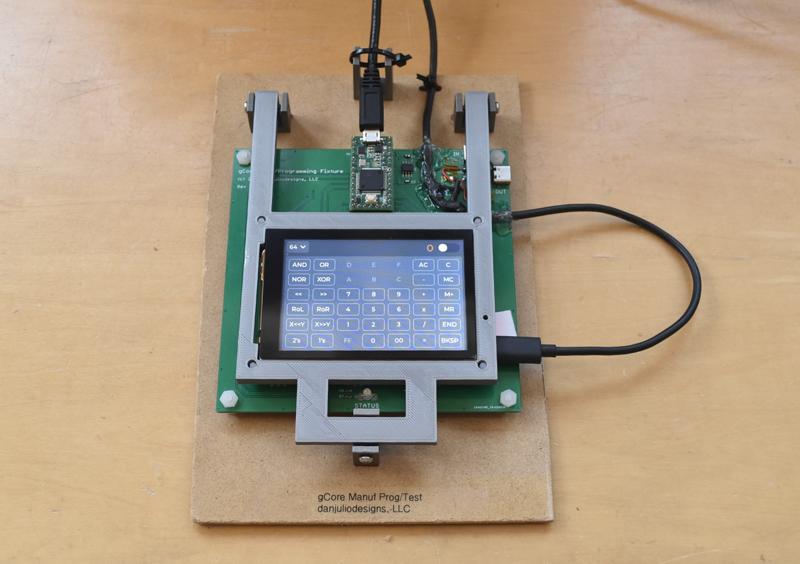
The hardware uses a PJRC Teensy 3.2 as a local controller with software running on a PC and connects to the gCore using a set of pogo-pins. A 3D printed mechanism holds the gCore down. The Teensy reads various voltages, outputs digital signals that control a simulated battery, power button and USB power supply, interfaces to the gCore I2C bus and implements a programmer for the EFM8. The ESP32 is programmed by the PC via USB.
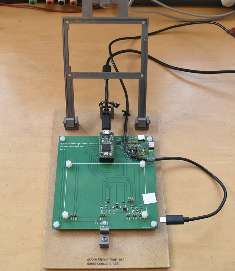
Originally I intended the switched USB connection to gCore to run through a pair of USB-C connectors on the test fixture PCB. However I got some signals reversed so the connectors didn't work. I ended up just splitting a USB cable open, cutting the +5 line and running that through the pair of P-channel MOSFETs on the test fixture used to turn Vusb on and off. And holding the cable down with lots of glue.
On the other hand the circuit I designed to simulate a LiPo battery worked really well. The test fixture has to handle both a drain and charge of a simulated battery. I looked into a dual quadrant power supply design but the complexity and cost put me off. Then I realized all I really needed to test was that the charger IC put out current. That could be implemented by simulating a battery at one voltage through a Schottky diode and then observing if the voltage went close to 4.2V when the charger was active when Vusb was energized. The diode prevents back flow to the 4V regulator.
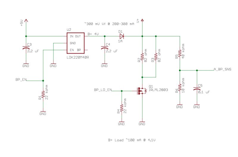
In the circuit above, +5V is supplied by teensy and U2 is a 4V regulator enabled by the Teensy using BP_EN. The voltage is routed through D1 to V+ which is connected to the battery input. When Vusb is supplied the charger IC on gCore will attempt to charge the battery to 4.2V. A small load is provided via Q1 so the charger sees some current flow. For a functional board V+ will jump from about 3.7-3.8 V to 4.1-4.2V when the charger is running and is sensed via A_BP_SNS.
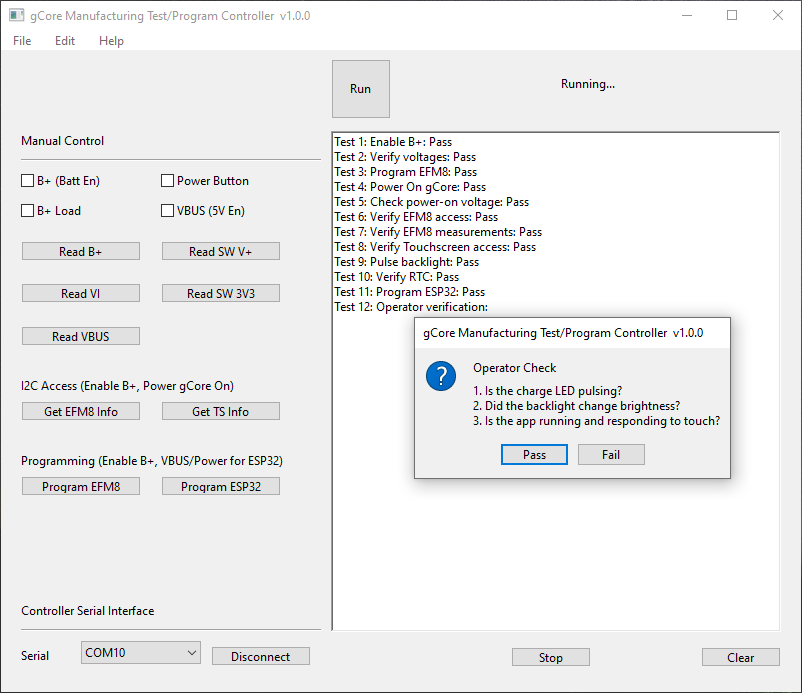
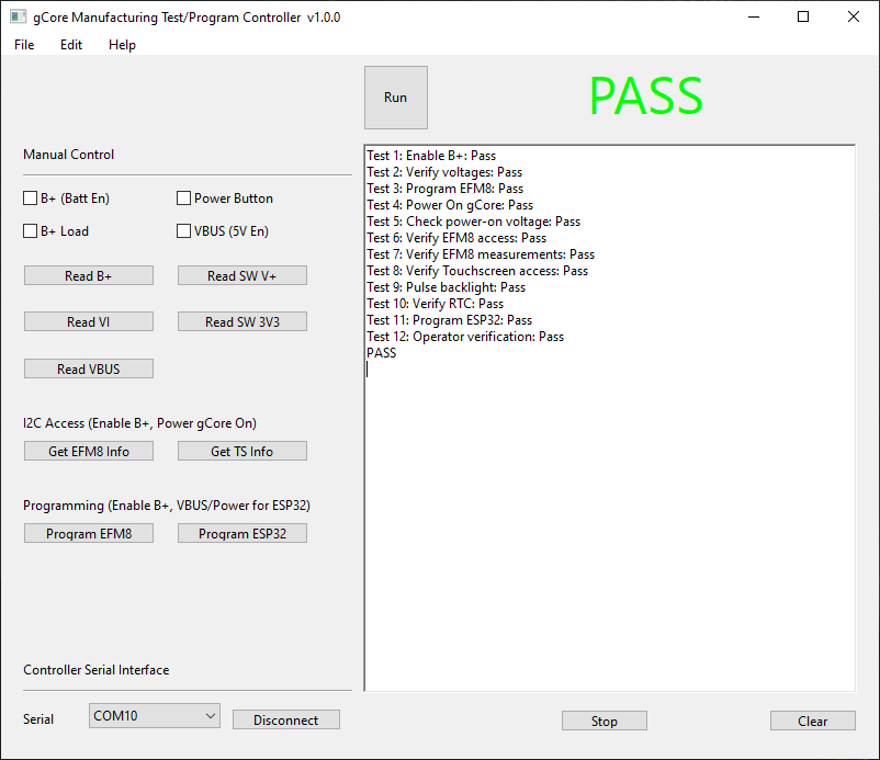
Software running on the Windows PC (and Mac, for me) was written in xojo. The program encapsulates the pre-compiled esptool binary I found in the ESP32 Arduino package and binary files for both the EFM8 and ESP32. Although it has a set of manual controls, during normal operation the operator only has to press Run and acknowledge one dialog box for each board. Excluding the time to insert and remove a gCore the entire test and programming process takes around 20 seconds.
I still have to write a document that correlates error messages with parts of the gCore for debugging of failed boards.
Discussions
Become a Hackaday.io Member
Create an account to leave a comment. Already have an account? Log In.