Close
0%
0%

SBC-T113 RGB/MIPI/LVDS/AMOLED/QSPI/MCU LCD

Allwinner T113-S4 SOC chip is a 2xCortex-A7+1xRISC-V+256M DDR3 processor with RGB_MIPI_LVDS_8080 LCD driver.

Similar projects worth following
Allwinner's newly released T113-S4 SOC chip is a dual-core 1GHz Cortex-A7+1GHz 64bit RISC-V+256M DDR3 processor designed for intelligent control and human-machine interface in automotive and industrial applications. It comes with 256MB DDR3 on-chip memory and H.264 video decodere and 2D graphics engine, and has a lead time of more than 10 years. We chose the T113-S4 for our compact SBC board, which has 4xUSB ports, 1x1000M network interface, 2.4G & 5G Wifi6/Bluetooch 5.4 modules and audio headphone output sockets, and an on-board microphone. An RTC battery socket is also installed to power the RTC of the SOC at 12uA.
It has lcd controller with max 1920x1080 resolution, capable of driving RGB/MIPI/LVDS/MCU8080 interface LCDs.Three LCD FPC sockets for RGB/MIPI/LVDS are installed on the SBC-T113.

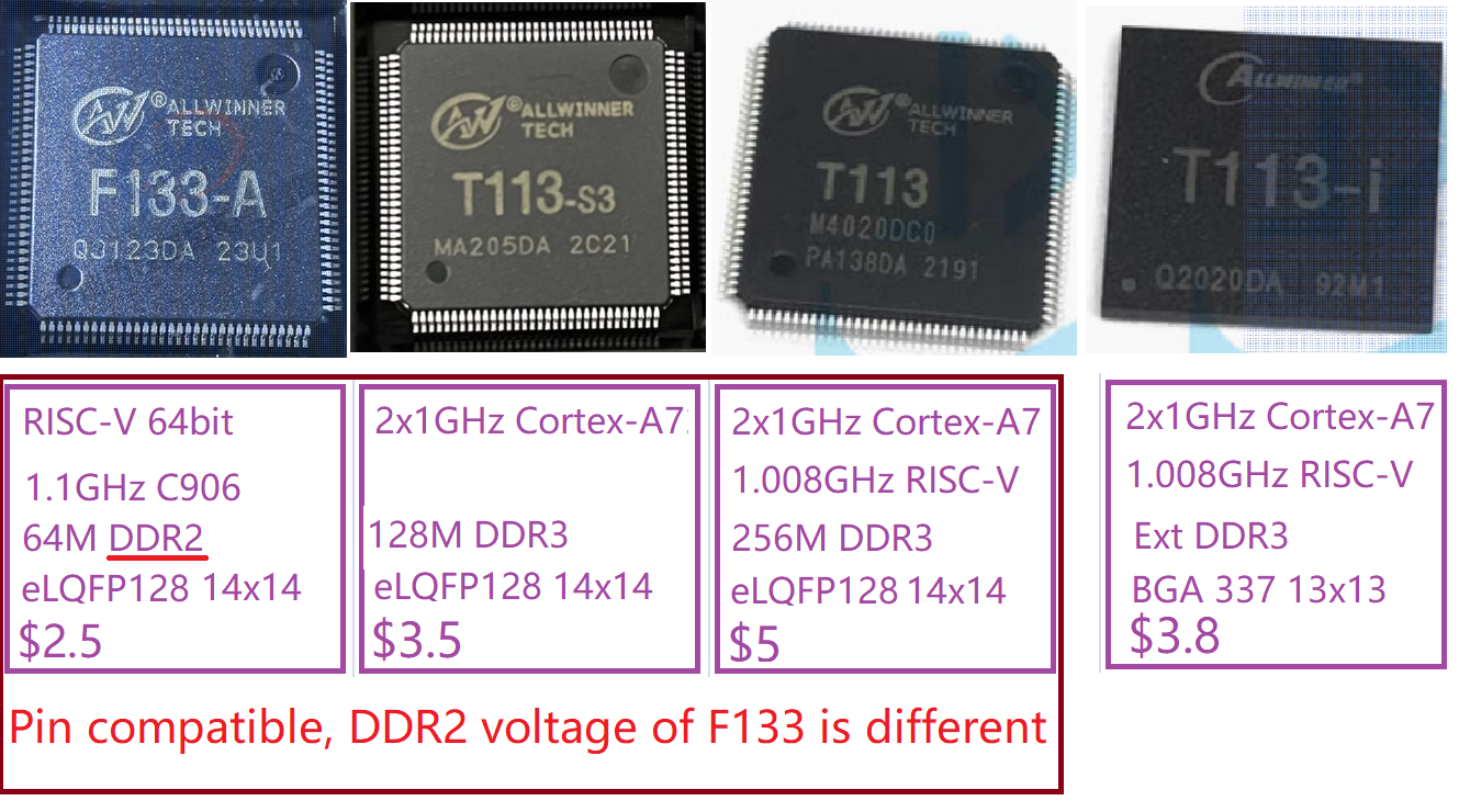
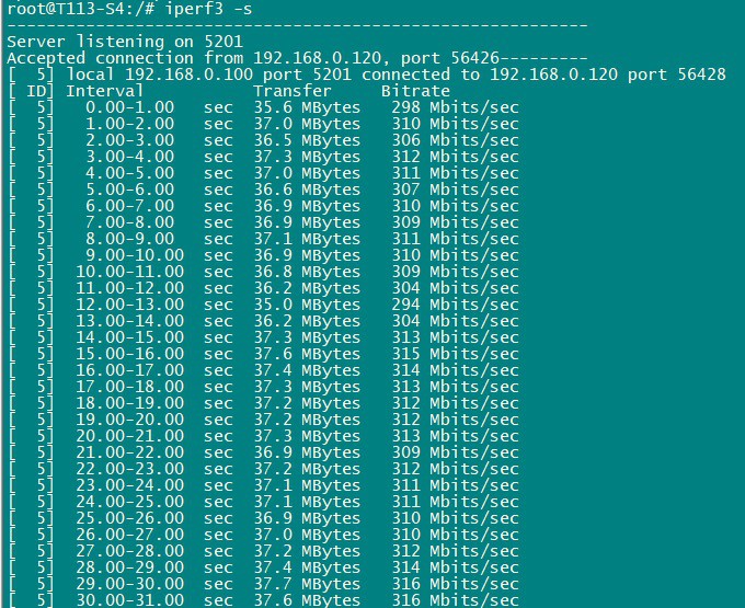
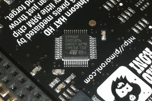
Allwinner Technology's newly released T113-S4 chip has an internal DDR3 upgrade to 256MB and a 64bit C906 RISC-V 1008MHz CPU for running freertos/nuttx.

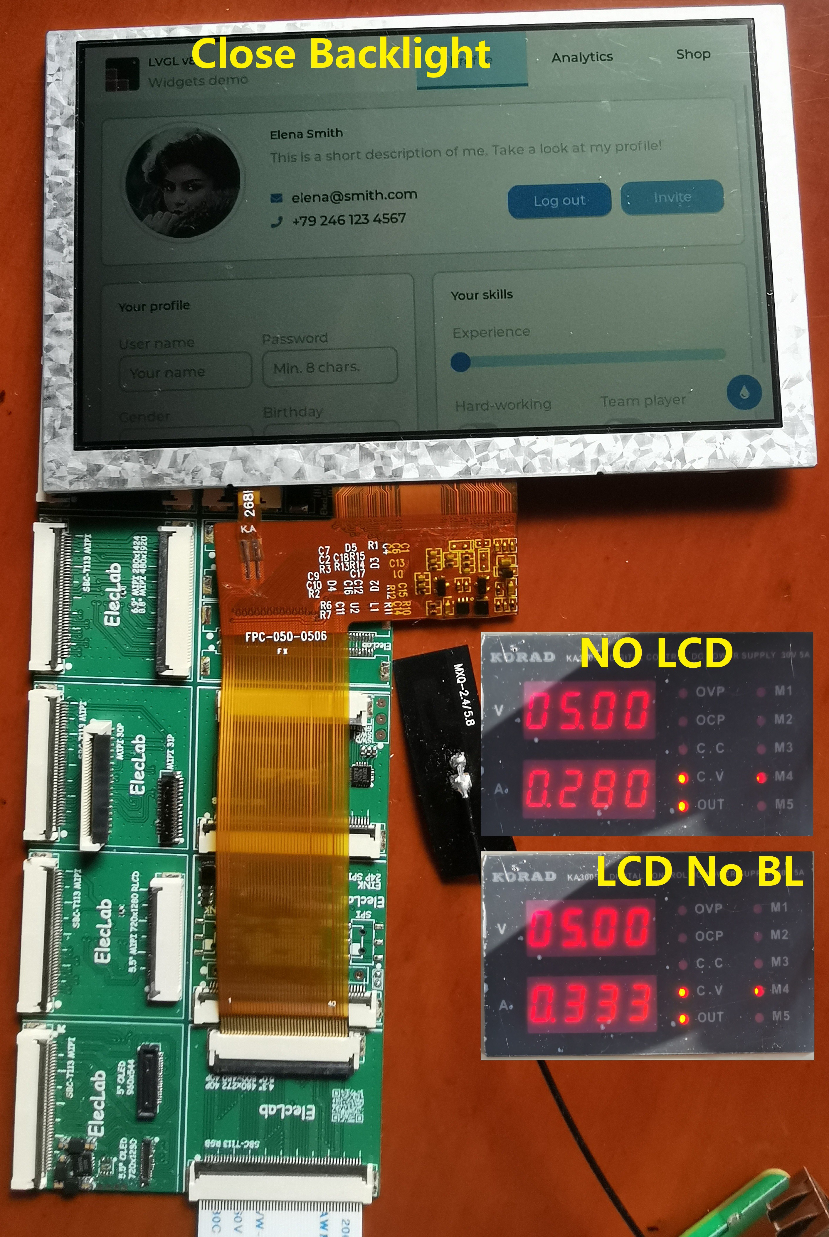
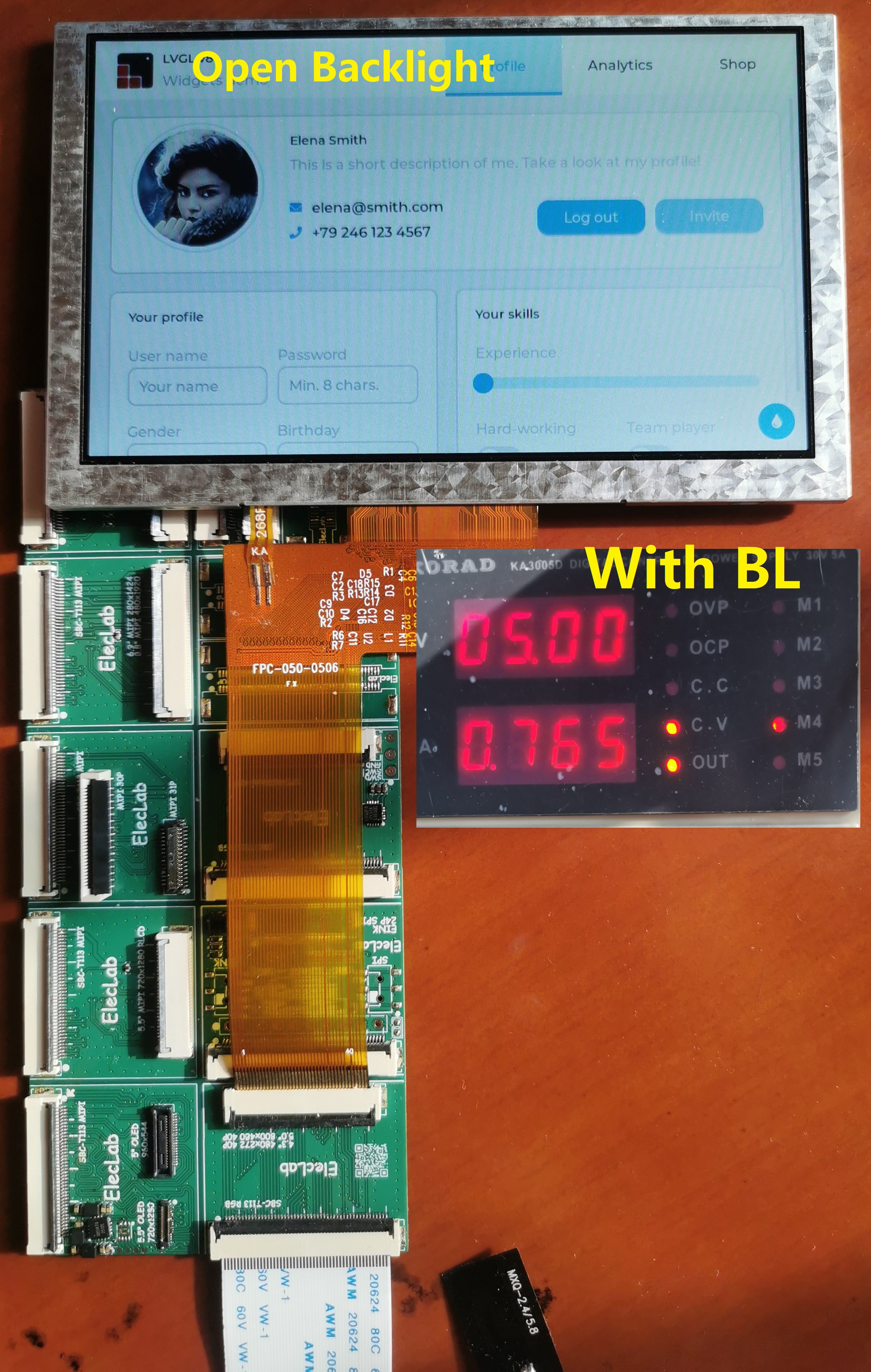
We have improved the SBC-T113 again, the LCD FPC socket has been changed to three types of RGB 50P/LVDS 40P/MIPI 40P, the wifi module has been improved to a 2.4G/5G dual-band Wifi6 300Mbits module, and a 512MBtyes/4GBtyes SD Nand chip has been added.

The pins of F133/T113 are compatible, but the DDR2 voltage of F133 is different.

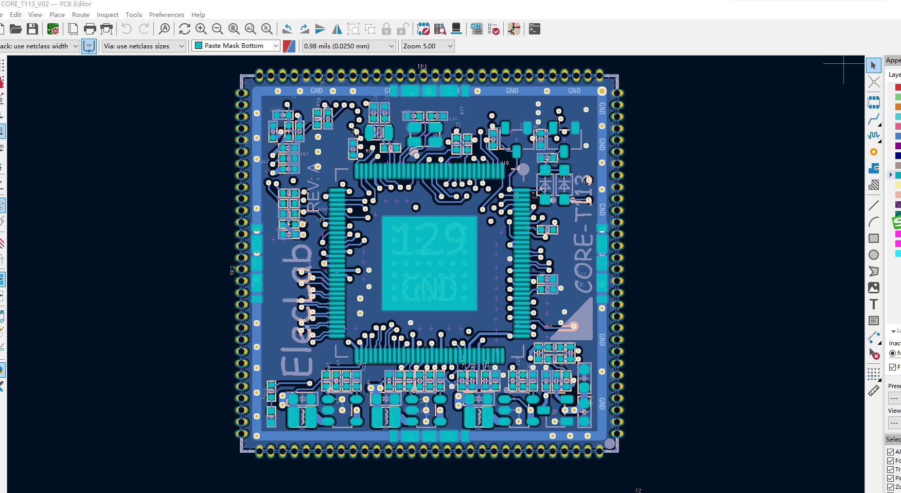
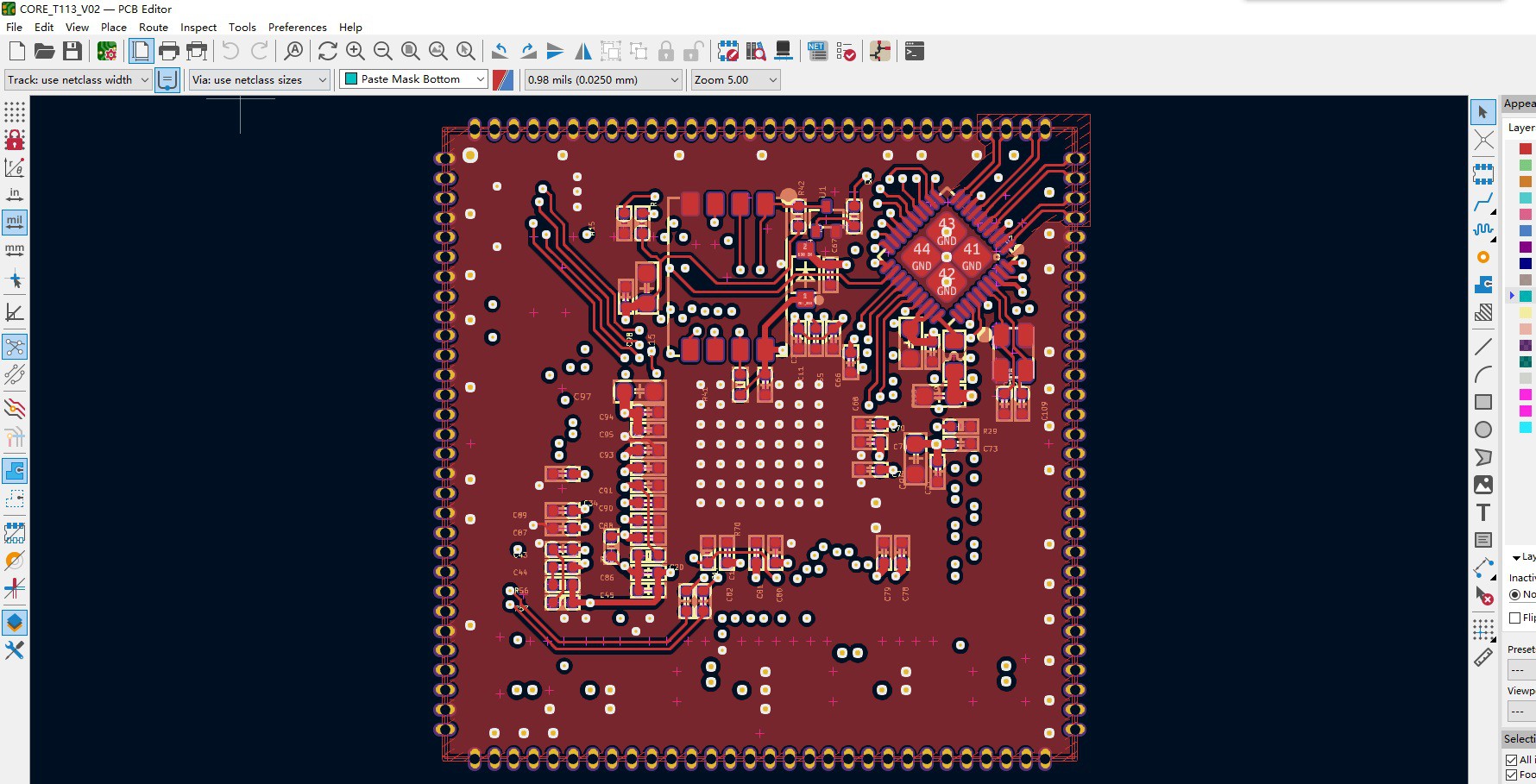
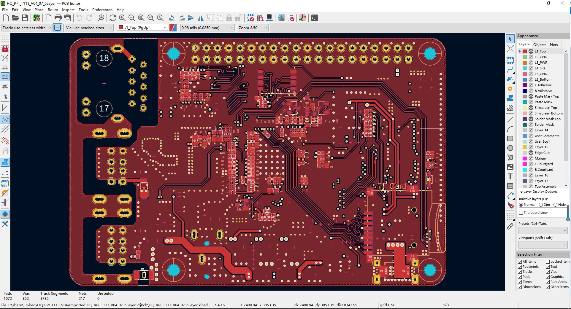
The PCB has been soldered.

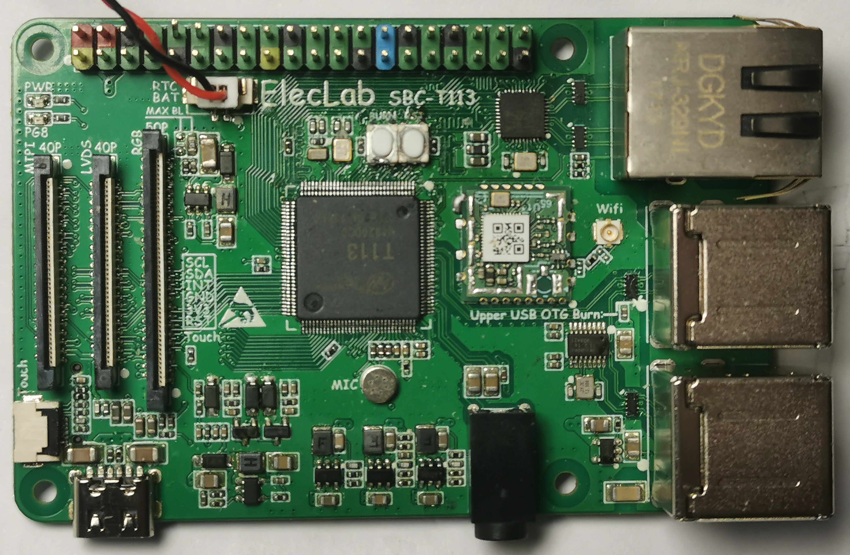
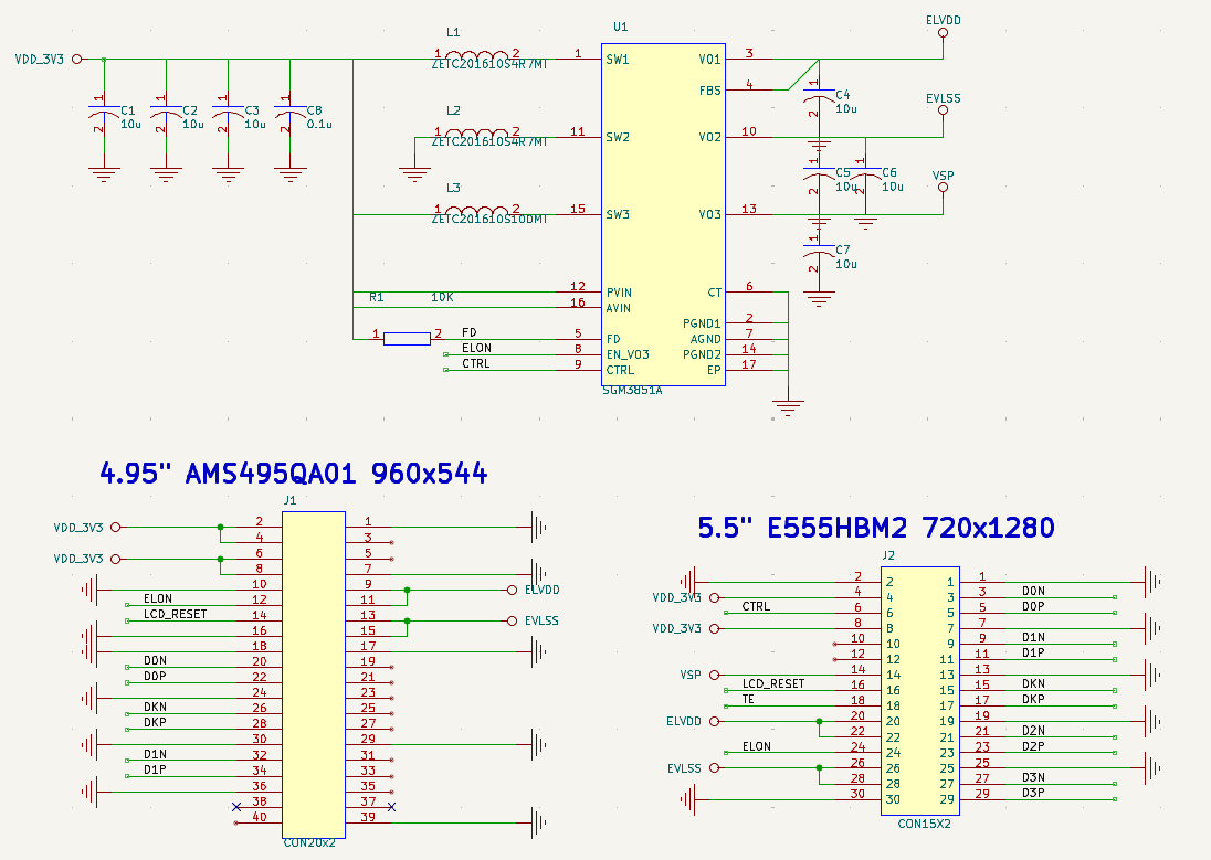
RGB/MIPI/LVDS three kinds of LCD sockets.

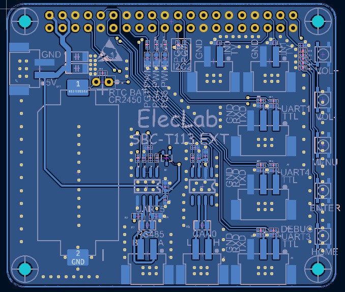
A new version of the SBC-T113 EXT has been drawn up。
1xCAN
1xRS485
3xTTL UART
5xAdc Key
2xAnalog Video Inputs
3xPWM LED
1xBattery Socket, CR2450 550mAh

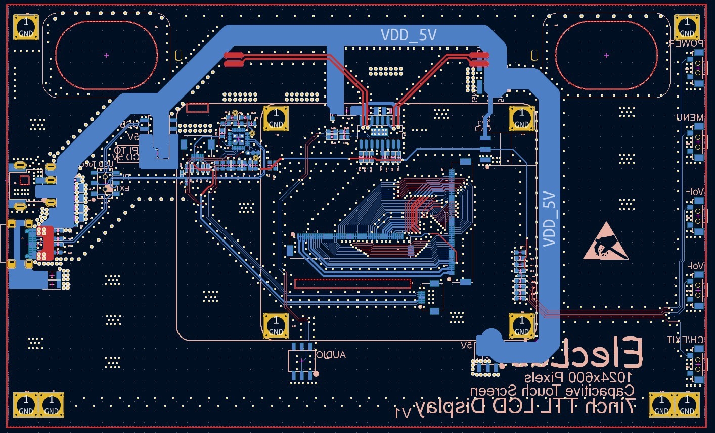
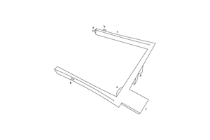
A standard 7” LCD PCB adapter board was designed to take 2 kickstands or mount an enclosure.

Similarity of mounting brackets

Similar for mounting housings

T113 Mounting Cover with Fan Attached

DSC00584.JPG

JPEG Image - 130.34 kB - 11/09/2022 at 08:02

Preview

DSC00574.JPG

JPEG Image - 122.56 kB - 11/09/2022 at 08:02

Preview

DSC00586.JPG

JPEG Image - 118.78 kB - 11/09/2022 at 08:02

Preview

DSC00582.JPG

JPEG Image - 63.09 kB - 11/09/2022 at 08:02

Preview

DSC00588.JPG

JPEG Image - 92.67 kB - 11/09/2022 at 08:02

Preview

View all 37 files

  • The PSV1000 screen AMS495QA01 960x544 is OK

    ElecLab12/28/2025 at 09:19 0 comments

    Another oled is also OK. The PSV1000 screen AMS495QA01 960x544 is set with the highest contrast ratio. The power consumption of this screen is relatively low. It only needs two voltages of ELVDD ELVSS, which is the same as the E555HBM2 voltage value, and is driven by the same SGM8351A power chip.

    AMS495QA01 video playback current is still low on a non-white background.

  • The 5.55" AMOLED of E555HBM2 720x1280 has been tested.

    ElecLab12/28/2025 at 04:16 0 comments

    The 5.55" AMOLED of E555HBM2 720x1280 has been tested. Now the contrast ratio is set at 50%, and the power consumption of all white is still very large. The conversion board uses 3.3V. If the contrast ratio is 100%, it will lower 3.3V. The power consumption of the screen is recorded.

  • Running LVGL and touch functions

    ElecLab12/22/2024 at 13:45 0 comments

    Compile the Audio mixer of lvgl demo. The GT9xx touch screen runs normally and displays normally. The UI uses the hardware rotation function of G2D and does not burden the CPU.

  • T113-S4 stamp hole core board

    ElecLab12/18/2024 at 02:58 0 comments

    Completed the PCB design of the stamp hole core board.
    Found a newly launched 32Gbits=4GBytes industrial temperature SD Nand, used it to load the Linux system, and integrated the RTL8211 1000M phy chip on the back of the PCB.

  • The PCB of T113-S4 has been completed

    ElecLab12/16/2024 at 00:51 0 comments

    The drawings have been updated, the PCB has been processed, and the next step is to verify the new functions of T113-S4.
    A core board was designed using KiCad.


    The PCB has been manufactured and is ready for components to be soldered.

  • Upgraded to 256M DDR3 T113-S4 chip and WIFI6 AIC8800D80

    ElecLab12/13/2024 at 09:08 3 comments

    We upgraded the hardware to use T113-S4, which has built-in 256M DDR3 memory and added a 1GHz 64bit C906 RISC-V processor, which can run freertos/Nuttx.
    We also upgraded the wifi module to the WIFI6 version of AIC8800D80, which greatly improved the wireless speed.

    When the wifi6 signal quality is high, the speed of iperf3 -c is around 270M and the speed of iperf3 -s is around 300M.

    Of course, a 512MB SD Nand storage chip is also installed for it, so that the system and programs can be solidified inside.

View all 6 project logs

  • 1
    5 RGB expansion boards and 5 MIPI expansion boards are designed to externally reflect LCD screen/AMOLED/QSPI screen/MCU screen/24P Eink screen.

    10 display expansion boards have been designed for SBC-T113, 
     5 kinds of 50P RGB expansion boards 
     1. 40P RGB888 socket (such as 4.3" 480x272/800x480, 5.0" 480x272/800x480/1024x600, 5.0" 800x480 semi-reflective screen) 
     2. 24P spi Eink socket (can be XH2.54 led out, or it can be QSPI function), using the special DBI function of T113. 
     3. 40P SPI+RGB666+6P capacitive touch screen socket (use $0.07 Cortex-M0 to initialize spi, support a variety of sizes and resolutions of LCD screens, and this kind of 40P LCD can integrate capacitive touch screen) 
     4. 30P/40P MCU 16bit socket (40P with TE foot with tear-proof function, and also supports more specifications of LCD screens) 
     5. 24P QSPI LCD screen socket (supports 1.8" 360x360 TFT round LCD screen, 2.13" 410x502 AMOLED square LCD screen) 
      
     5 kinds of 40P MIPI expansion boards 
     1. 30P/40P AMOLED socket (5.5" 720x1280 AMOLED, 5" 960x544 AMOLED) 
     2. 30P RLCD socket (5.5" 720x1280 full reflection LCD screen) 
     3. 30P/31P MIPI socket 
     4. 40P MIPI socket (supports 8.8" 480x1920 HSD088IPW1-A, 6.9" 280x1424 MIPI screen) 
     5. 40P MIPI socket (supports 8" 800x1280, 10.1" 800x1280 LCD screen)

    The picture below is a 5-inch 800x480 semi-reflective LCD screen.

    The picture below is a 5.5-inch 720x1280 full reflective LCD screen.

View all instructions

Enjoy this project?

Share

Discussions

Similar Projects

Does this project spark your interest?

Become a member to follow this project and never miss any updates