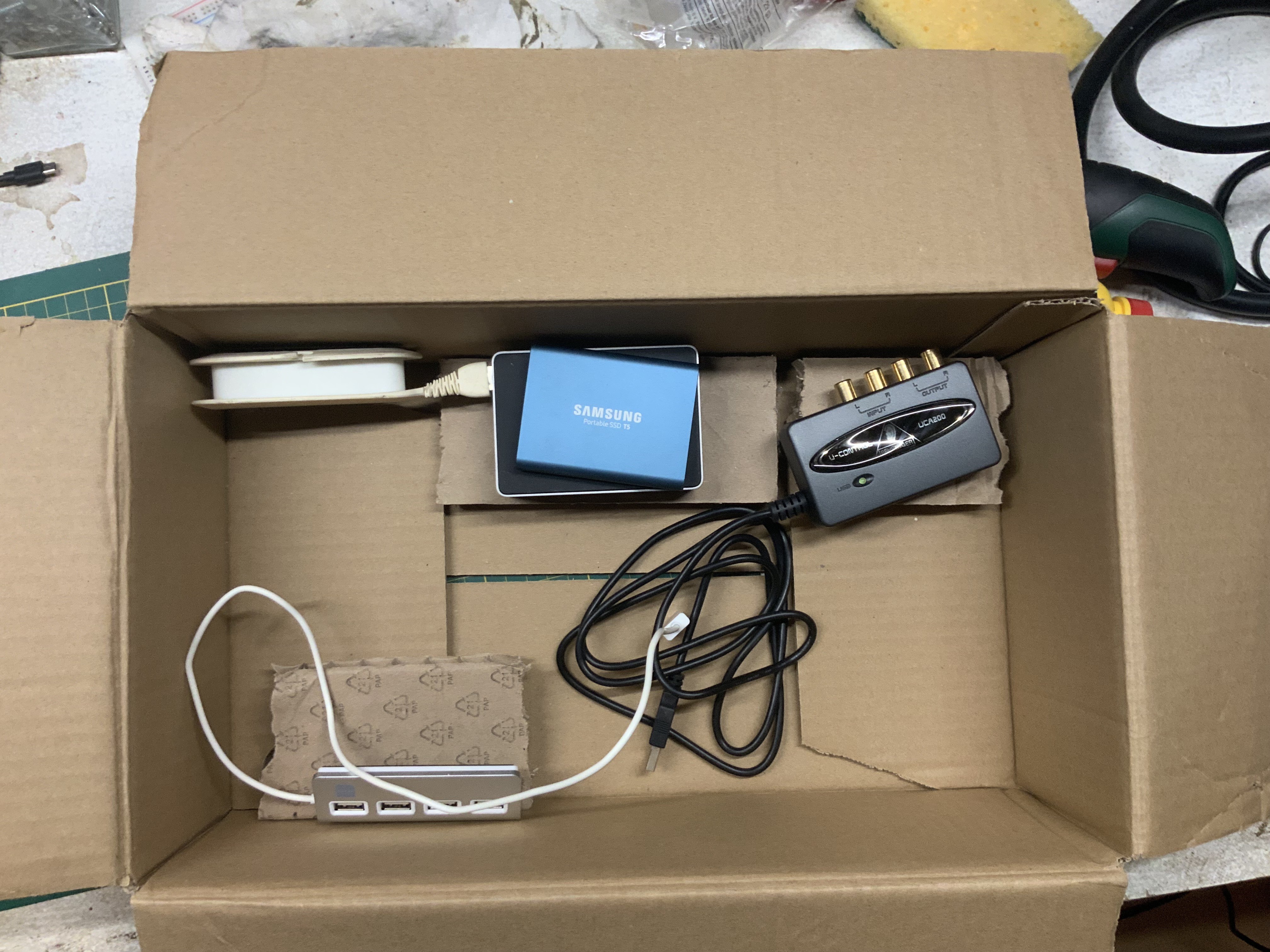
I think I found a workable setup for all the current components in the box. I'm going to skip the USB hub at the front for now because this also should tie in with my front faux 90's desktop design. The basic layout is pretty simple.

This is it basically. Ignore the aluminium USB hub at the front at the moment. That is where that SSD is going to go. This was one of the various mock-ups I did earlier before going mental with glue and tape on the box, but this pretty much shows what I can work with.
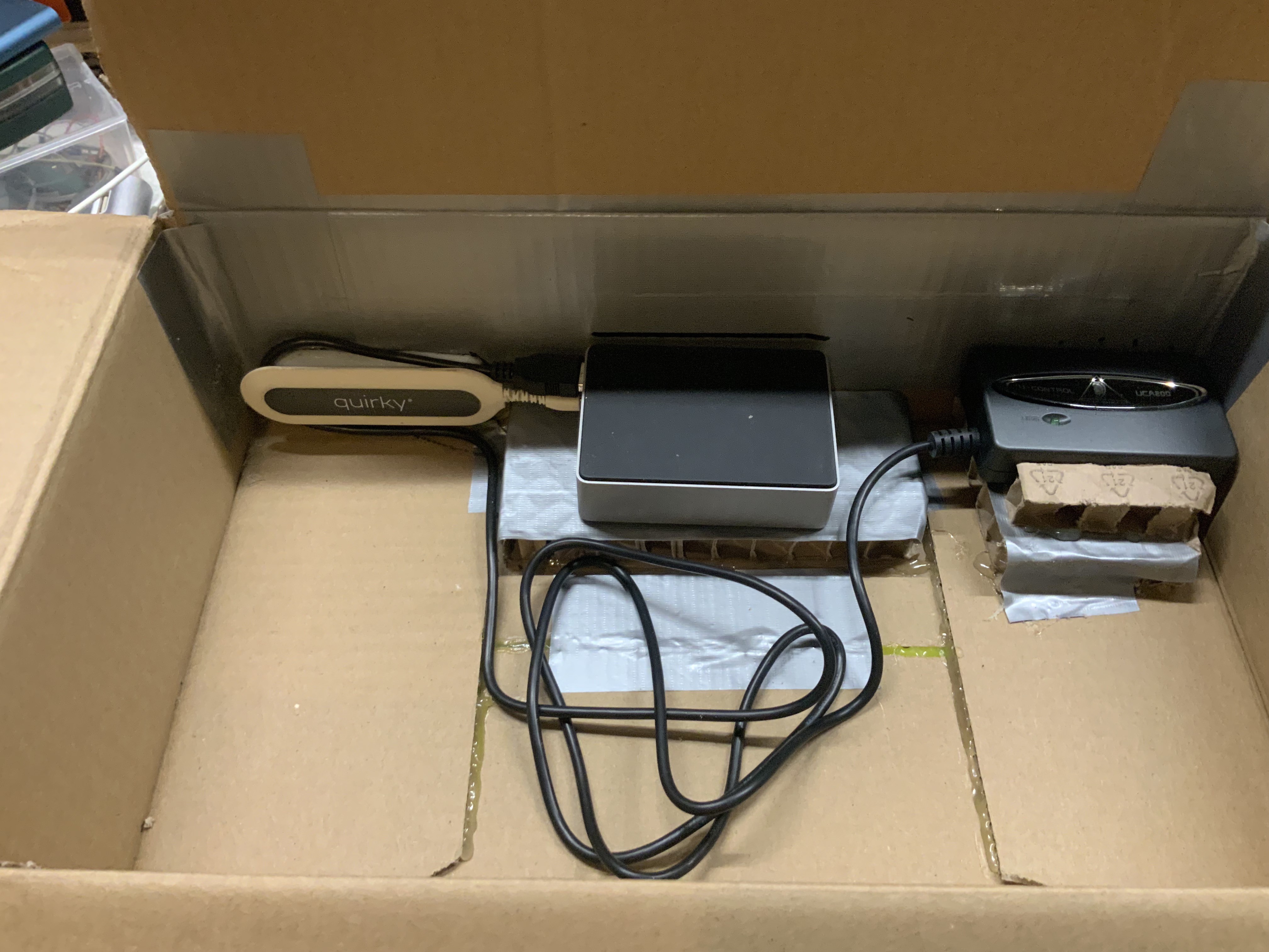
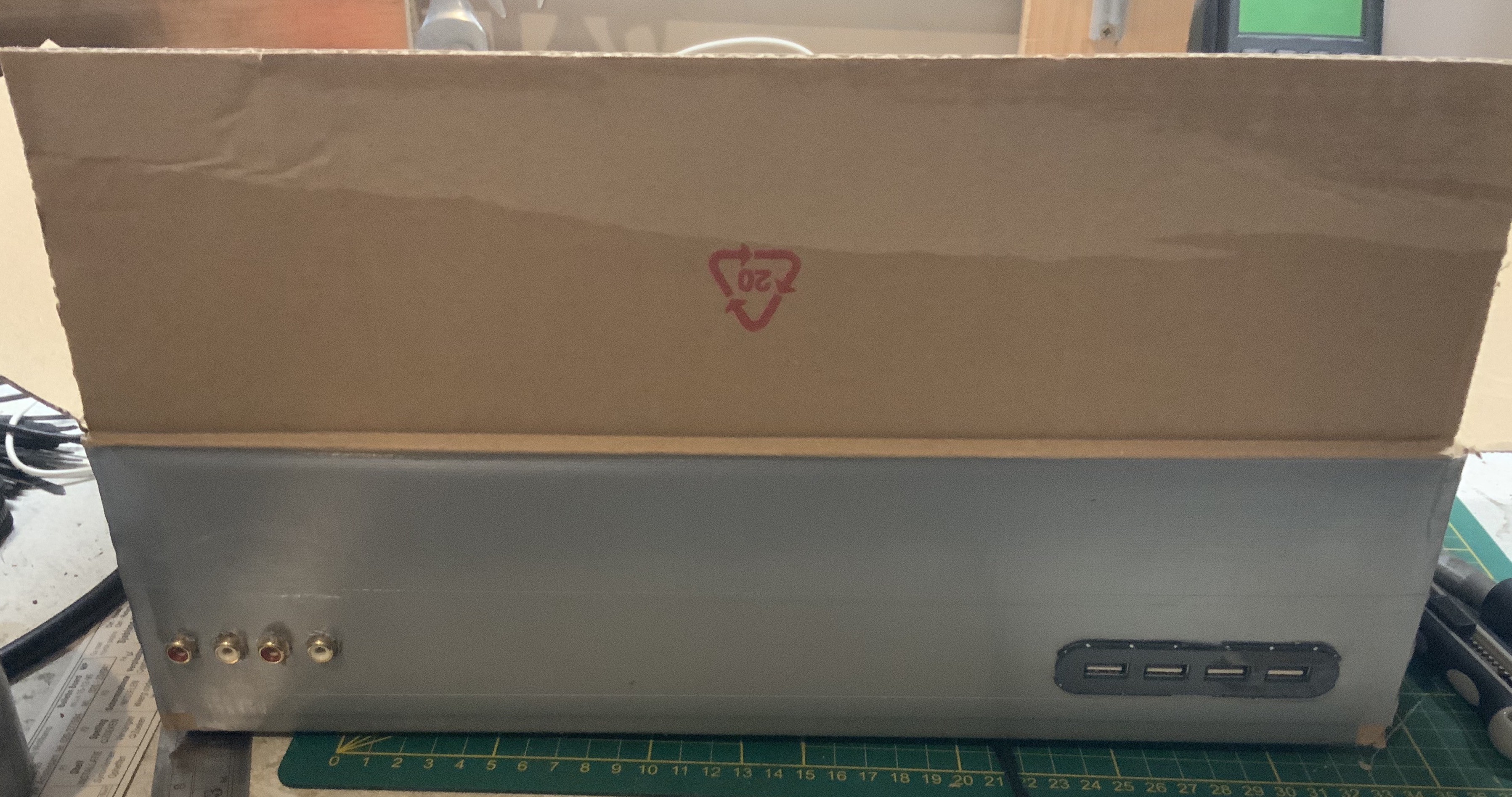
I first installed the audio device by cutting out 4 holes and mounting it on a plateau. It has a fixed USB cable, so tie-wraps are in order there. The USB hub for the back will connect to the slower USB2 port on the RPi. It can twist and I can make a snug fit hole for it. The connectors for the RPi are exposed via a simple square cut out. Here you can see these components roughly in place.

Everything but the RPi itself is fixed reasonably well here. It all is just friction fit, hot glue and duct-tape. At this point, this has been one of the least harmful cases I have ever worked on! There is always the risk of a paper cut of course, but there are no metal burrs in here at all!... Yet... Here is what the back looks like without the cut out for the Rpi : Until the next log, I'm out!

 Timescale
Discussions
Become a Hackaday.io Member
Create an account to leave a comment. Already have an account? Log In.