 NuclearPhoenix
I finally came around to finish the PCB layout for the latest (and probably last honestly) hardware revision of the Mini SiD. In short, this is a small-ish quality-of-life update with some nice changes that should make it easier to use, while still not changing a whole lot fundamentally.
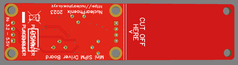
This is what the new PCB looks like, I still need to get the OSHWA certification for this again, so the files are not completely final, altough everything's functional. The files and all the additional info can be best found on GitHub: https://github.com/OpenGammaProject/Mini-SiD

Changes in this revision:
- Switched from a 2-layer PCB to a 4-layer PCB for much better signal integrity.
- Improved PCB layout and shielding in general.
- Decreased length of the electronics section by 2 millimeters.
- Slightly more filtering for the SiPM output voltage.
- Consolidated all the diodes to use the same chip to reduce BOM clutter.
- The pulse discriminator reference, input resistor and power supply feedback path all now use much tighter tolerance resistors with less temperature dependence. That way it's less susceptible to temperature changes.
- The pulse discriminator range has been slightly decreased for easier setting the correct voltage.
I think these changes are a great way to expand upon the last version that already worked well enough to be usable. It also marks a great point to say this project is more or less completed. It's usable, it works great and IMO there is not much that can be changed anymore without some fundamental changes. So thanks to everyone for your support and posting your interest and suggestions. Feel free to continue doing so!
There will be one update when the OSHWA certifies the hardware again, so expect that in the next couple of days.
Discussions
Become a Hackaday.io Member
Create an account to leave a comment. Already have an account? Log In.