Finally, after releasing the new Open Gamma Detector hardware I have time to work on this project some more. In the past months I've already worked on the newest board improvements and here is a complete update to reflect all the changes.
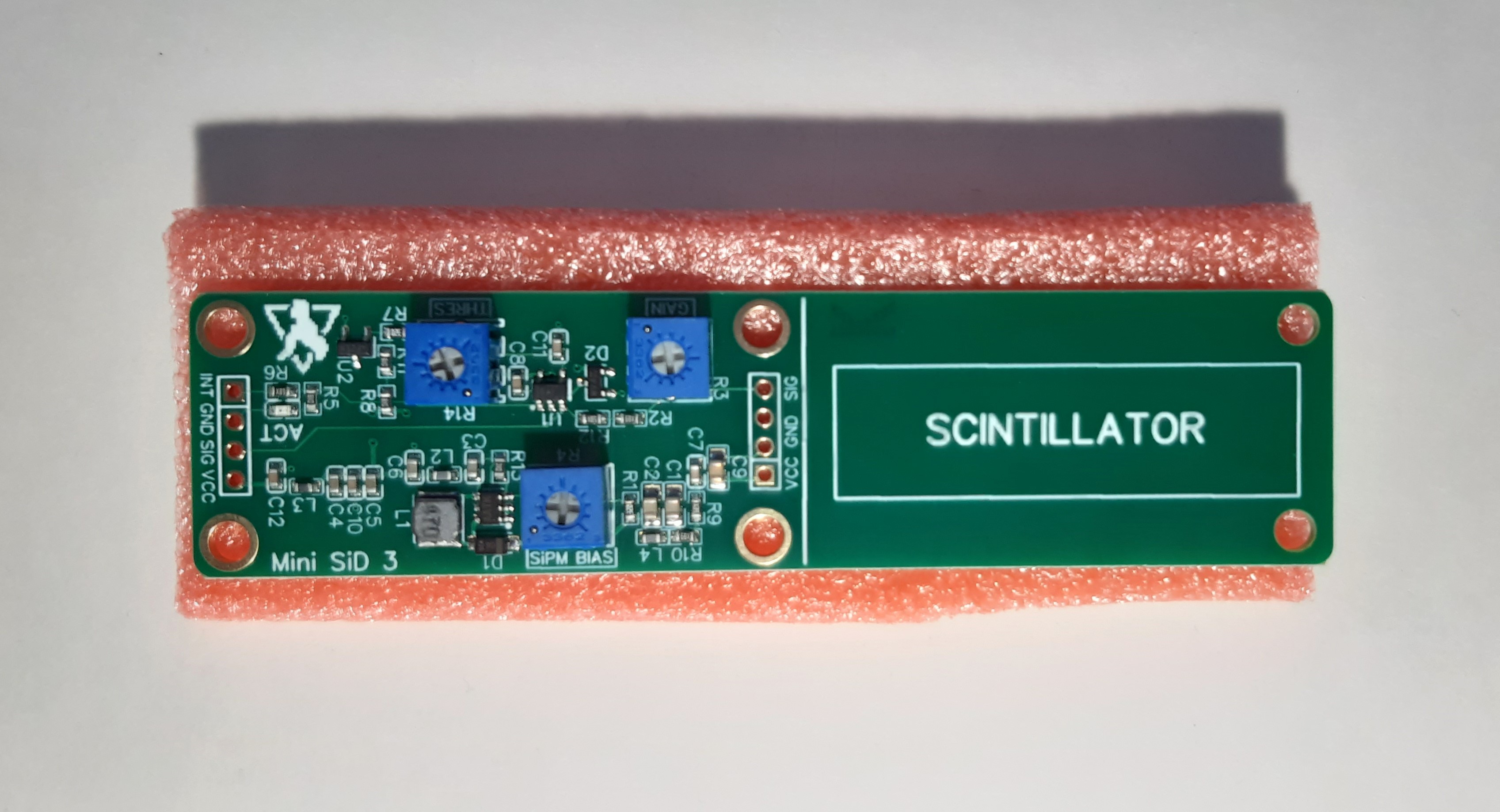
The overall footprint hasn't changed, but the electronics area is now a bit smaller meaning you have more space for the scintillator. This is due to the change from 0805 passives to mostly 0603-size components. Here is a photo of the a new board:

Fully soldered board with mounted scintillator/SiPM combination and some pin headers for easy prototyping:

Now, what you're probably interested in the most is what has changed? Why a new revision, right?
So here is a list of most of the changes between revisions 2 and 3:
- Switch to 0603 components for smaller size and better layout.
- Optimized component values for lower power consumption.
- Removed unnecessary amplifier (preamp) at the SiPM output.
- As a result of that, the board is a bit cheaper now and consumes less than half the power it did before: ~4.5 mA @ 5 V vs. ~12 mA @ 5 V in normal operation with the SiPM @ 30 V. Most of the remaining power goes to the low-noise SiPM power supply.
- Slightly larger SiPM output voltage range.
- Added the ability to extend the pulse duration with the gain pot so that it's easier to work with slower microcontrollers.
- Some more power filtering.
- Improved silk screen for better readability (the old one was a mess).
- Removed the AC coupling for the threshold comparator. This didn't really work as planned anyways and introduces some more problems (activity dependent thresholds and stuff).
- Removed the weird notch on the PCB cutting edge.
Basically, it all comes down to the power usage, size and also general usability. That are the most important changes to the new Mini SiPM Driver board.
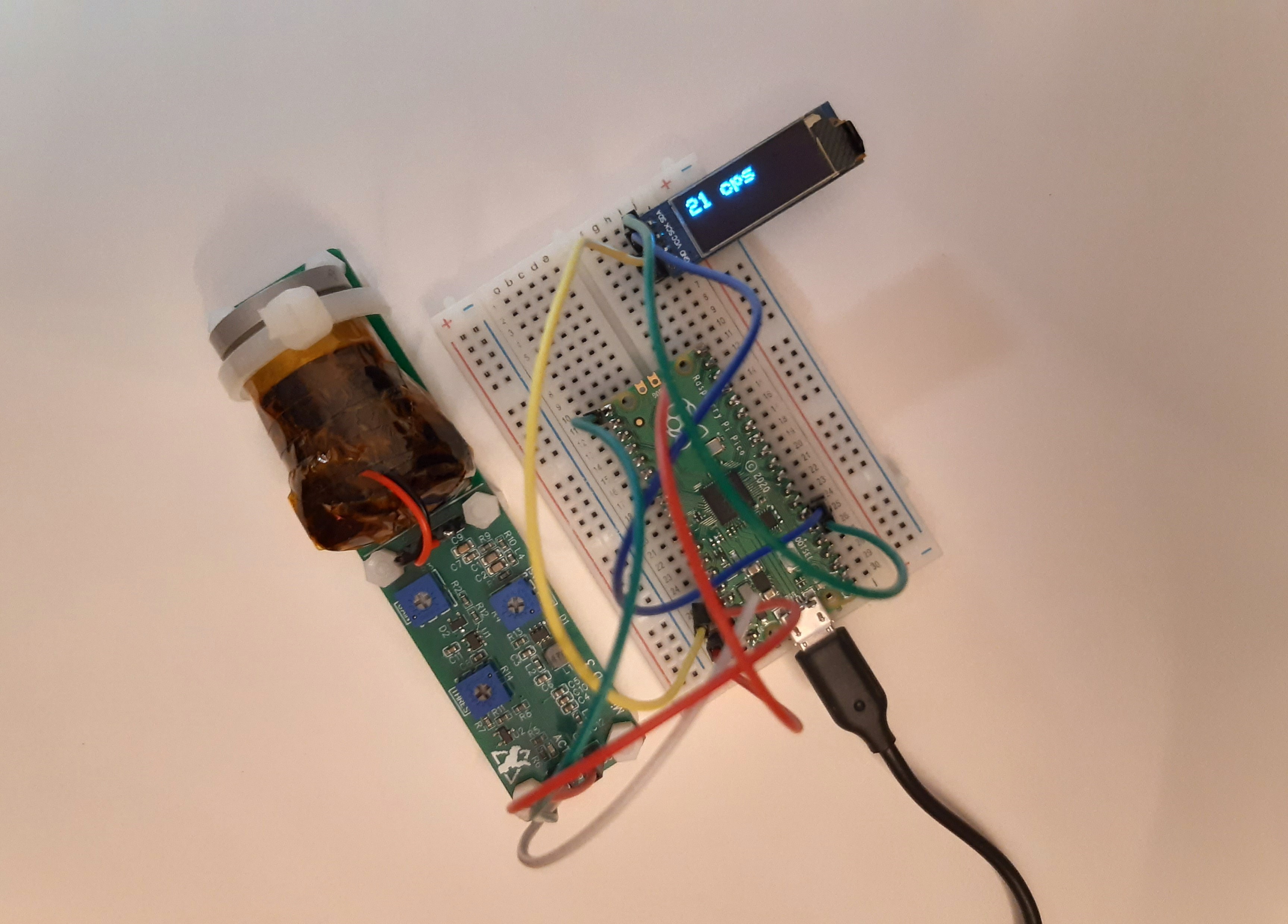
Here is my simple scintillation counter demo with the Mini SiD, a cheap $5 OLED and a $5 Raspberry Pi Pico. You don't need to use a Pico if you want to save power -- you can always increase the gain to also extend the pulse duration at the same time. Digital pulses can be easily as long as 10 µs which can be fairly easily picked up by microcontrollers. The example sketch can be downloaded on GitHub!

Fully assembled boards will very soon be available on Tindie and the makerfabs store too. Once it's up all the links on here will start to work. As always, feel free to build it yourself and use Kitspace to support them too! Speaking of Kitspace, it seems like they're taking a while to refresh all the new hardware, so please be patient with them ;)
I'm excited to see what you're using your Mini SiD for! Feel free to send me images of your projects, feedback on the hardware or anything else related to the project really. Have a nice day!
 NuclearPhoenix
Discussions
Become a Hackaday.io Member
Create an account to leave a comment. Already have an account? Log In.