Close
0%
0%

Phased array sonar

DIY sonar with 24 channel receiver and active transmitter with 1 (up to 4) channel

Public Chat
Similar projects worth following
Learn radar/sonar, both passive and active. Design different phased arrays, 1D, 2D and create an algorithm platform that can be used to evaluate performance.

* Phased array design, beam patterns and frequency evaluation
* Beamforming (mainly FFT based) 1D, 2D.
* Algo processing, both signal processing (filtering) but also image processing to enhance imaging of the data
* UI showing channels, frequency spectrums, beam formed data (polar coordinates), in 2D and 3D.

Hardware will be a combination of custom PCB's, arduino-style devices (because they are cheap), microcontrollers, audio-interfaces (sample rate 96kHz or less), computer and software written in Java and CUDA.

Basically, a platform for testing strange ideas around radar/sonar/audio that involves an array of receivers and transmitters.

Quick introduction can be seen here: https://www.youtube.com/watch?v=z4uxC7ISd-c

Introduction and direction

Introduction video describes an approach that is different from the current project:

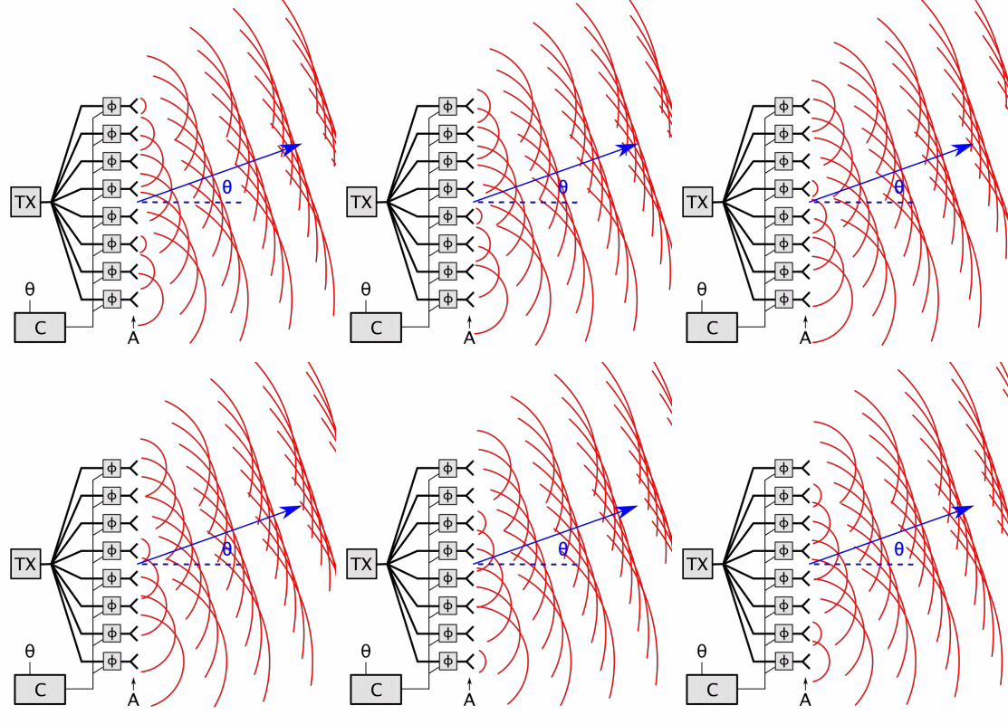
  • Active transmitter is a 1D array, used to focus "energy" or sound is a specific direction.
  • Receiver is a simple mic that captures the echos from the direction of the transmitter.
  • Transmitter is sweeping across the area of interest. The larger the area, the more "pings" is needed, the longer time it takes to generate a full image of the area of interest. This means that number of pings required to generate an image, limits the fps.

The current project uses a different approach:

  • Transmitter is either a loudspeaker or a ultrasonic 40kHz transmitter. 
  • Receiver is a 1D array, consisting of 8-24 elements. The larger array is, the more narrow beams, but also more processing time.
  • Receiver is recording all channels, converts data in IQ, beamforms and shows the result. Processing is heavy, which is why I use the Nvidia GPU to do the heavy-lifting. By using the GPU, we can achieve FPS around 10, meaning near realtime imaging.
  • Transmitter can be replaced with an active array. If placed perpendicular to the receiver array, it will allow for capturing data in 3D. Either via sweeping or via multi pings combined. This is done by constructing the FM sweeps (pings) with different frequencies and using match-filtering to separate the pings in the resulting echos. Computational load will increase by the number of transmitter beams. 

Phased array design
Phased Array Design

Hardware

Hardware

Pulse design

Pulse design

Signal processing

Signal processing

Beamforming tests
Beamforming tests

Gerber_PCB_mic array 8ch max9814_2022-11-24.zip

Gerber for PCB

Zip Archive - 12.72 kB - 11/24/2022 at 10:17

Download

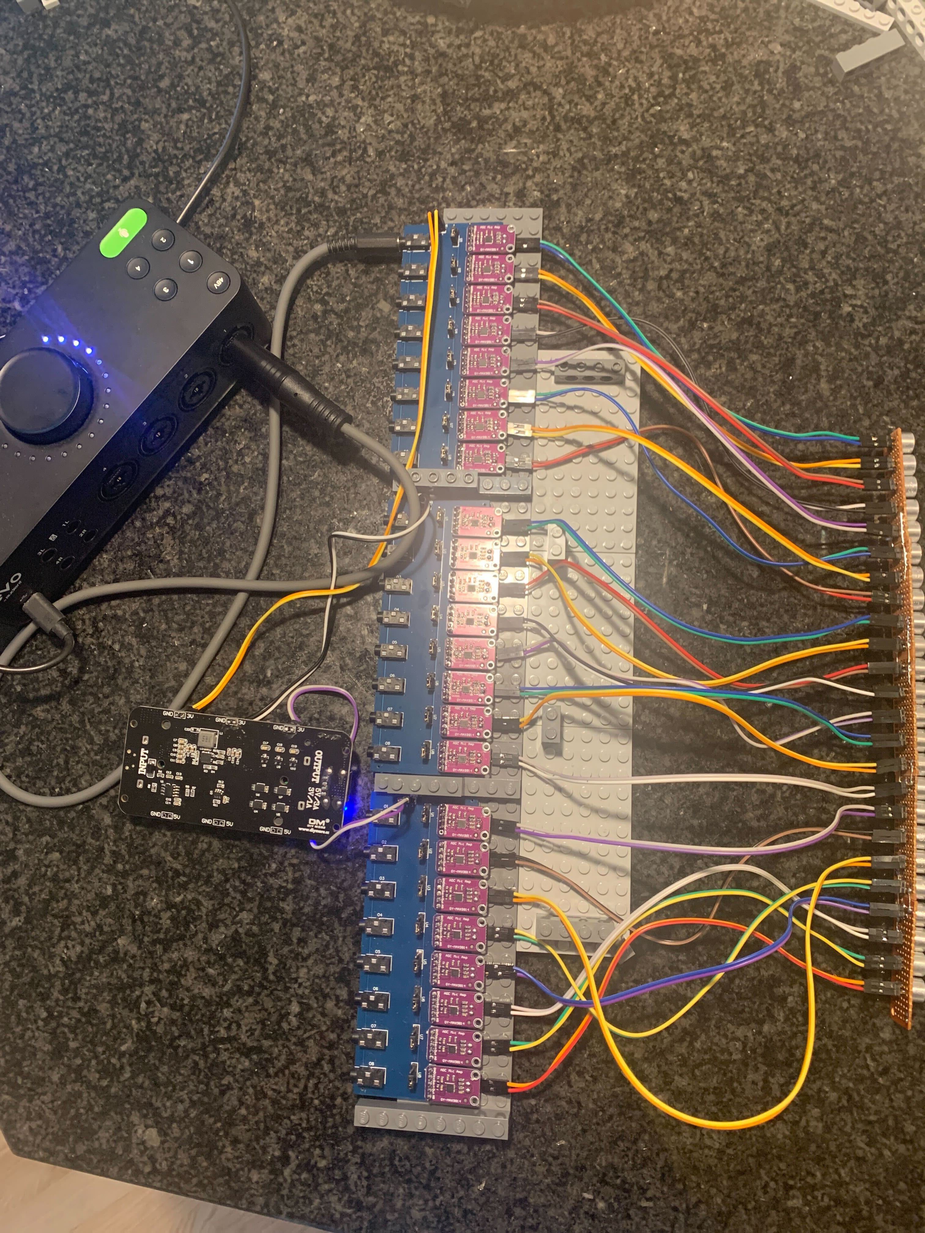
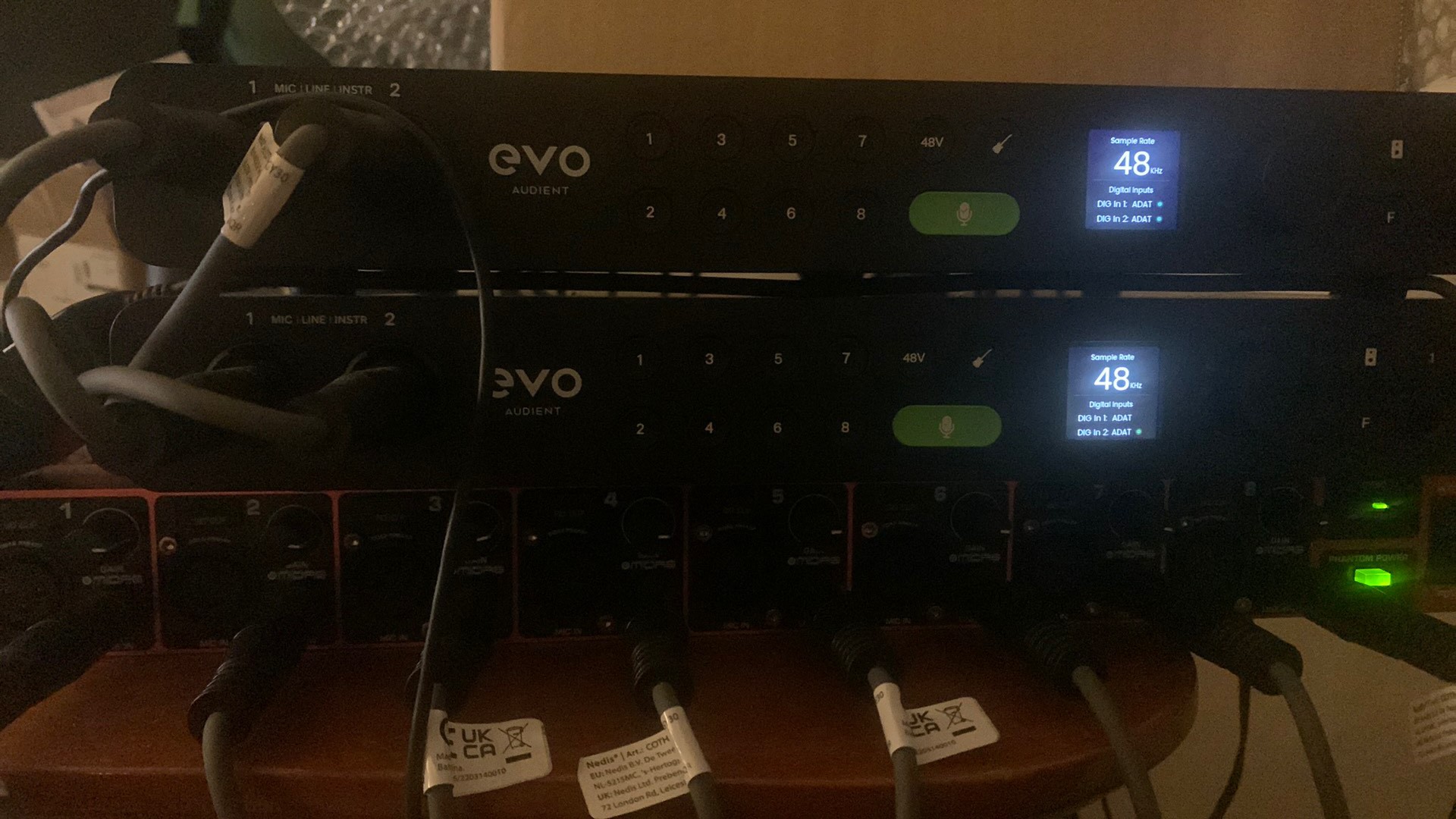
  • 3 × ADA audio interfaces, each handling 8 channels in/out. 2x EVO16 and 1 Behringer ADA8200. One of the EVO's are connected via USB to the computer. All ADA interfaces are connected via TOSLINK (ADAT)

  • Video of array in full function

    null111/23/2022 at 21:58 0 comments

    Video of me sitting at 1.1m -17deg (or so) , moving my hand at 0.8m towards the center at 0.6m -2deg and back.

    Video is processed with image enhancement and stacking algorithm, to reduce noise. I will add more videos in the future.

  • Updated signal processing page

    null111/23/2022 at 15:08 0 comments
  • Sampling gear

    null111/21/2022 at 23:12 0 comments

    Picture of my sampling gear

    or maybe it was just a test of the Hackaday mobile app...

  • 4ch hydrophone array

    null111/21/2022 at 23:05 0 comments

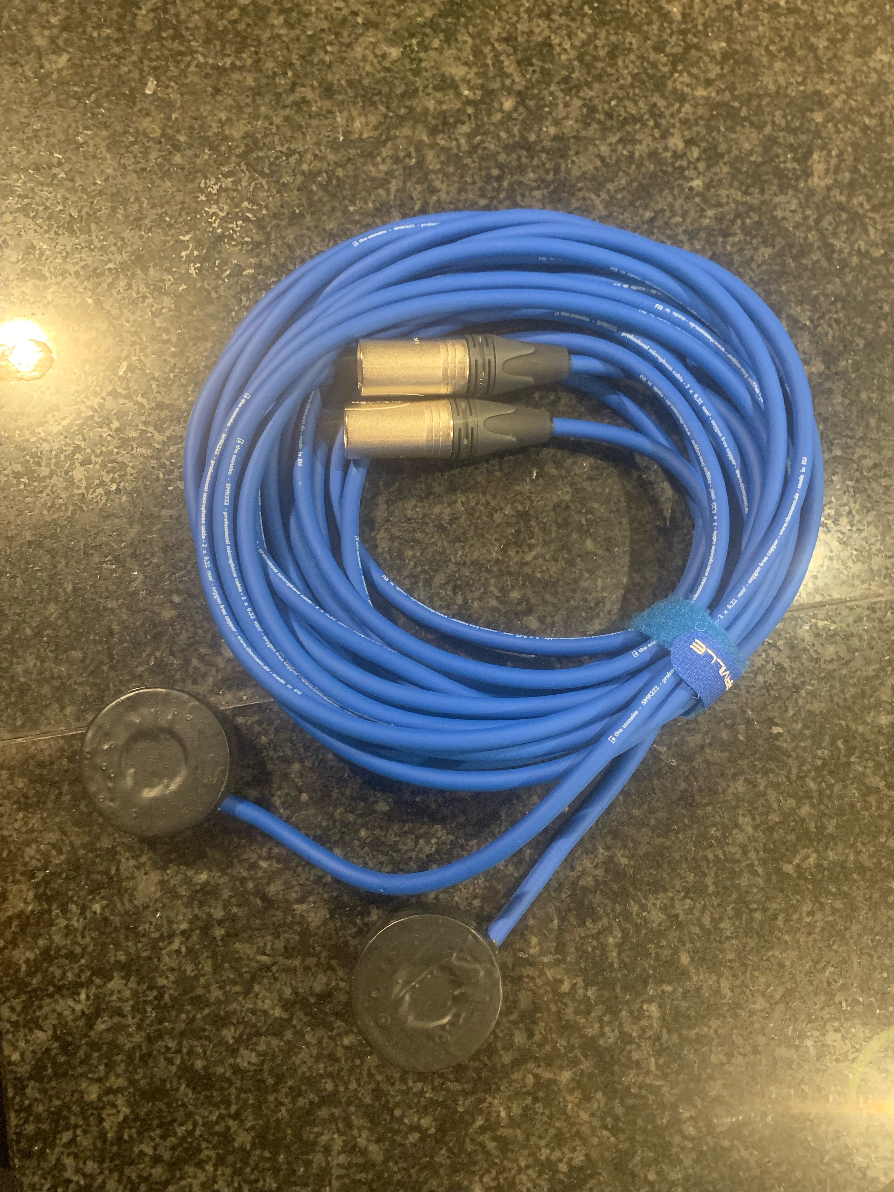
    I received 4x hydrophones for an upcoming experiment. I plan on aligning them with element spacing of around 15cm, bring the frequency down to 1-5kHz. It wont have a transmitter making it listening device only. 

    2 hydrophones

    Hydrophones are going to be used with experiments of detection where underwater sounds are coming from. 

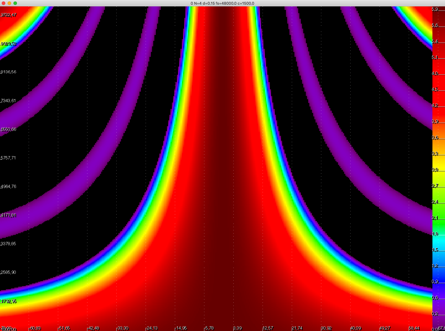
    Beam pattern would look like

    Frequencies below 5kHz and above 2kHz would give a reasonable direction ability. Whale songs is in this range.

    So when weather gets better, I will take my EVO8 (channel sampler), my laptop, on a field trip to the local harbour.  

  • Element spacing of 1cm is either too narrow or too wide

    null111/21/2022 at 22:36 0 comments

    Experiments with the new 24ch 1cm element spacing array is too narrow or too wide.

    Since it cant be any narrower, because mics' are 1cm wide, I am thinking about going back to 2cm spacing, extending the 16ch array to 24ch.

    Why?

    Beam radiation pattern for 1cm spacing, puts transmitter pulse frequency around 20kHz. 20kHz is nice, because you cant hear it, or.. at least I can't. (anymore).

    But my crappy speaker have a hard time dealing with the max frequency spec'ed (or maybe its my cheap-o-film gaming amp that is garbage. Frequency response is dropping off a cliff fast around 20kHz, so transmitted pulse energy is really weak.

    So, either I will go back to my 2cm array, where frequencies lie around 8kHz-14kHz, which is audible (nice for debugging, but annoying in the long run. Maybe I will also have problems with the CW pulse length being too short. 

    Or, I buy new amp, speakers.

    Or,  go for 40kHz range and use the cheap ultrasonic receivers and transmitters from SR04, which will require some clever arrangement of the receiver elements (and width is 1.6cm) since element spacing need to be 0.5cm.

    For now, I will keep the current, and soon I will go back to 2cm element spacing.

  • 24 channel 1D array

    null111/17/2022 at 21:02 0 comments

    Assembly and sound testing my 24 channel array. 

    Element spacing has been changed to 1.01cm, which allows me to use pulse frequencies 18kHz-22kHz. This should give better range resolution, narrower beams, if my speakers can handle the frequencies.

    Going ultrasonic, around 40kHz, would require me to reduce element spacing. With the current microphones, thats not possible. 

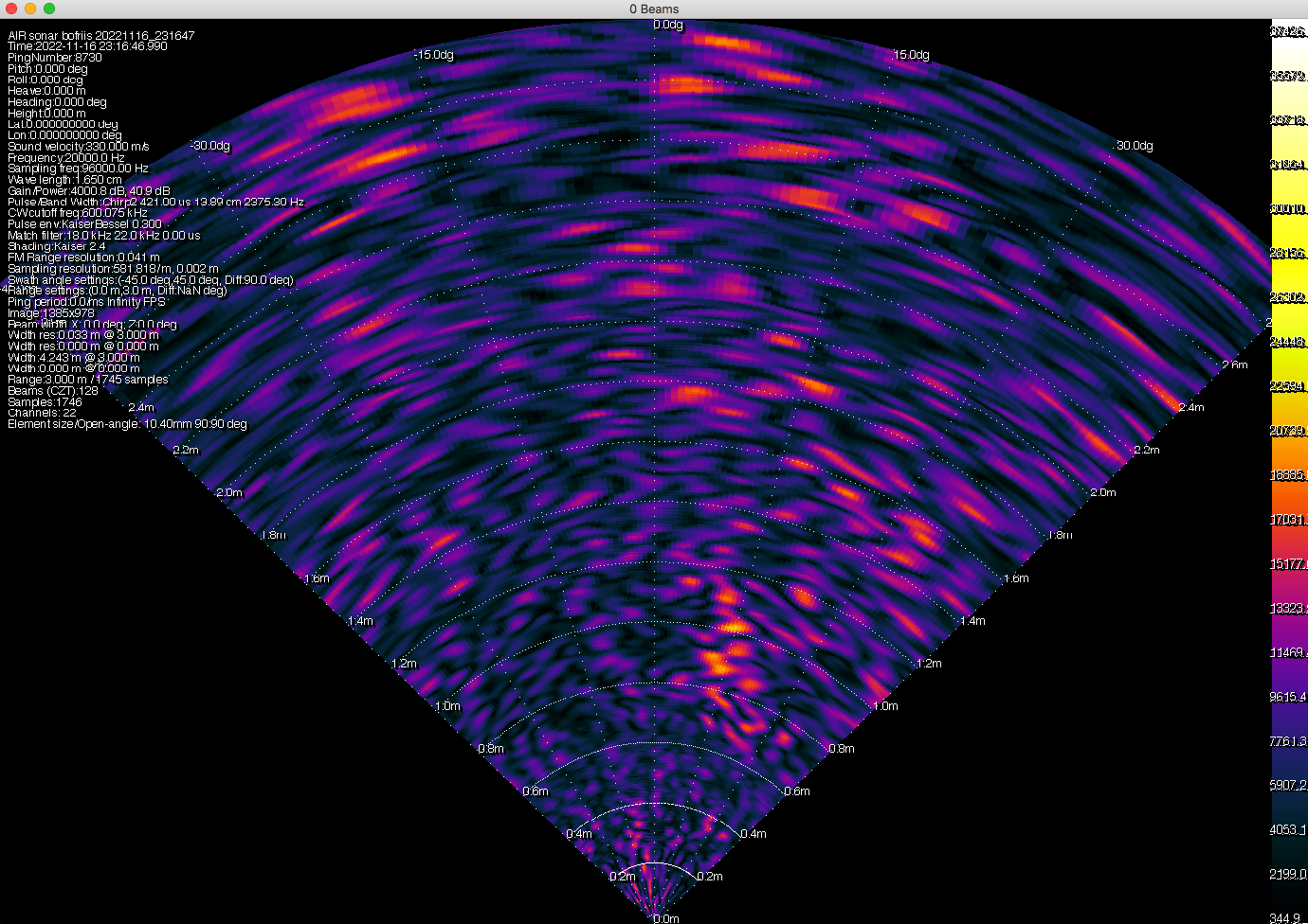
    First test:

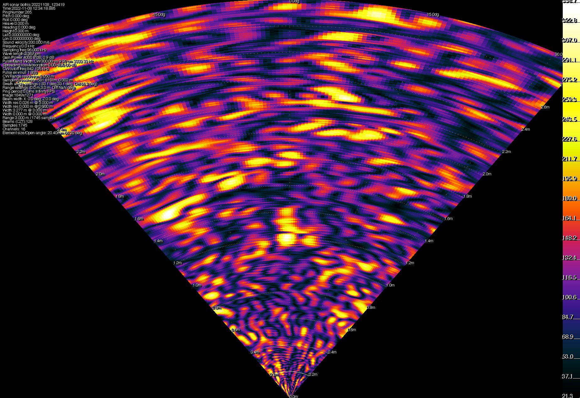
    Anything above 2m, are reflections i.e. multi-path. To the right, at around 1m, there is a chair and a wall. There is a lot of "tuning" ahead. Image seems a bit noisy. Some of the noise are coming from side lopes, some are multi path.

  • Updated array design

    null111/12/2022 at 08:32 0 comments

    Added beam radiation patterns

  • Updated the hardware page

    null111/12/2022 at 07:39 0 comments

    I added schematics for the PCB and PCB layout plus some pictures

View all 8 project logs

Enjoy this project?

Share

Discussions

Similar Projects

Does this project spark your interest?

Become a member to follow this project and never miss any updates