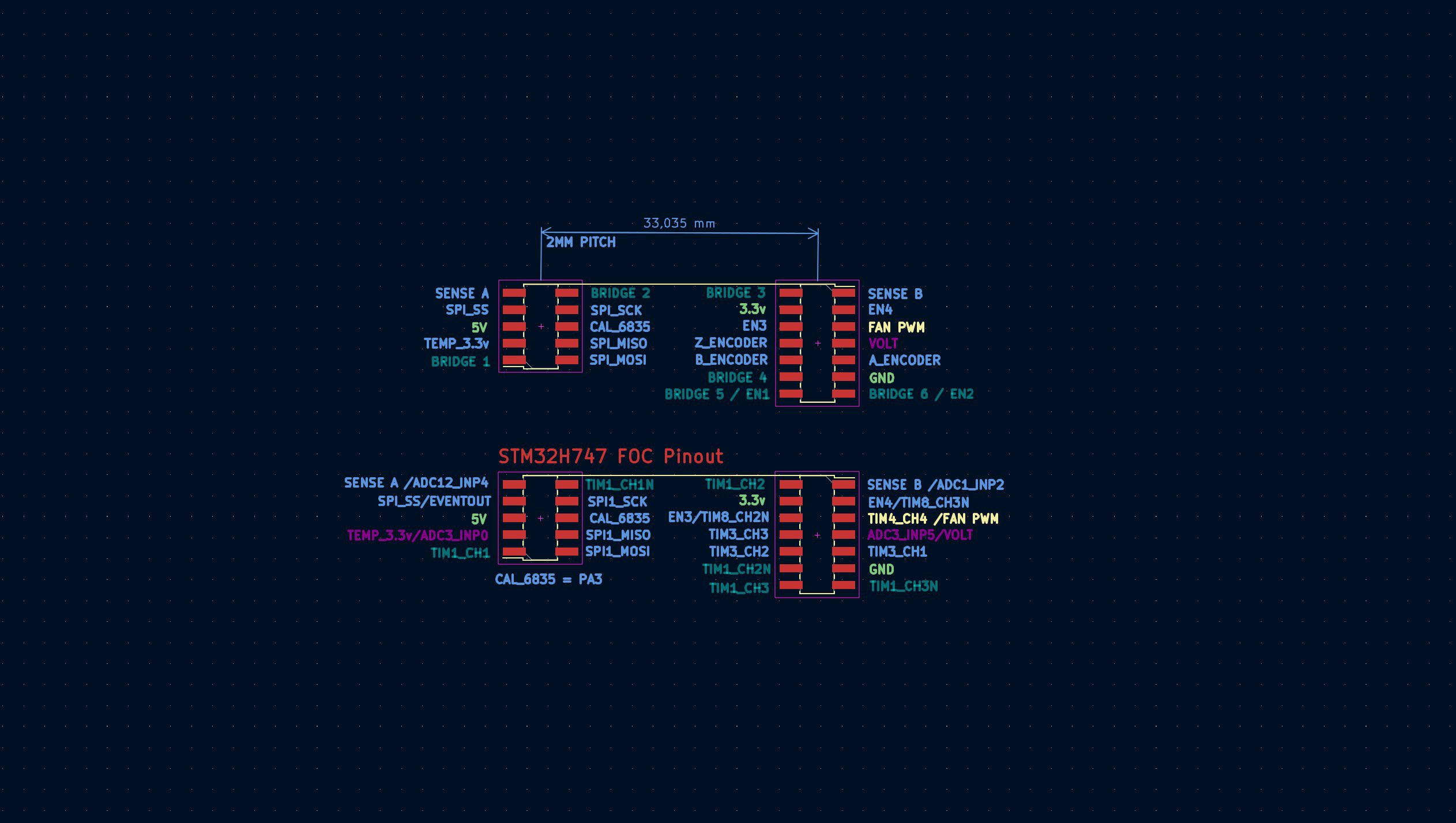
The two current sense ANALOG input´s are assigned to ADC12_INP4 and ADC1_INP2, which should make it possible to use the dual ADC mode, for simultaneous samples.
That leaves ANALOG temperature (thermistor) port and ANALOG voltage_divider (BUS voltage) port on ADC3.
The HALL and ENCODER interface is on TIM3 CHA 1-3
All BLDC PWM signals are on TIM1 (Advanced Timer). Supports 4PWM stepper and 6PWM BLDC.

 Juan-Antonio Søren E.P.
Discussions
Become a Hackaday.io Member
Create an account to leave a comment. Already have an account? Log In.