charliex
-
ballscrews n stuff
08/24/2015 at 18:16 • 0 commentswhoops
made a dent in the insulation and then bounced off across the room
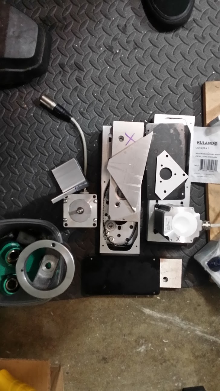
mmca and I (and mr pika) stripped the G0704 down to its barebones, making two piles of parts one for not getting reinstalled and one for reinstall. i won't go over it here, since (a) we didn't take photos and there a gazillion videos of that already.
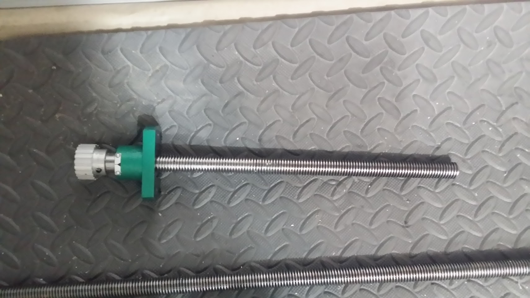
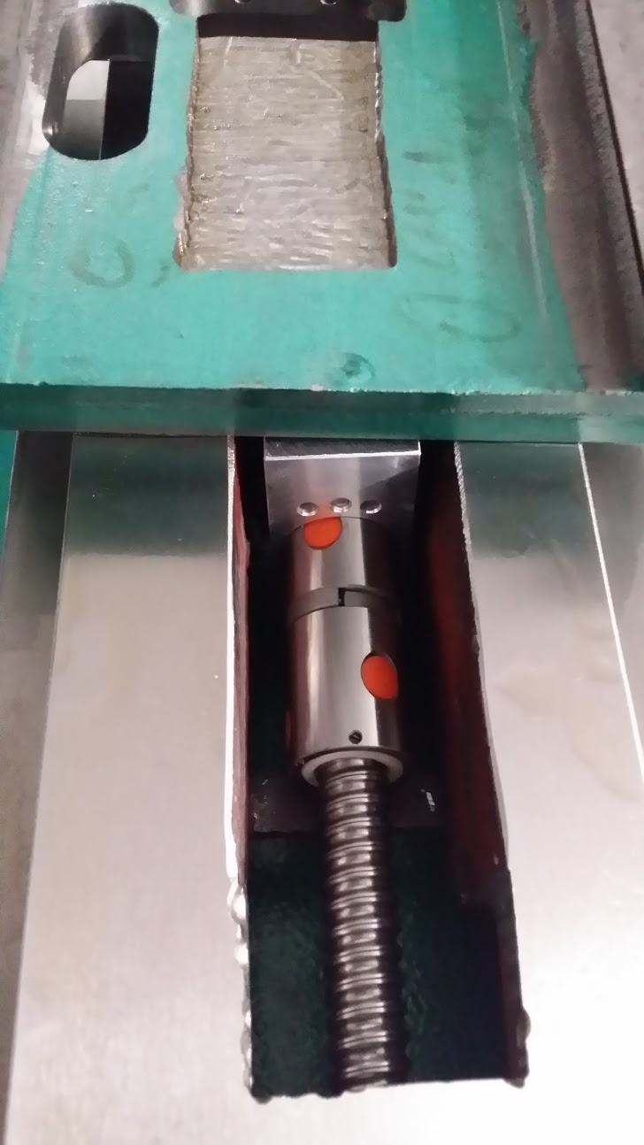
initially we took the ball nuts off backwards... again internet. those are the 3d printed holders made out of glow in the dark pla.
the pile of not going back, with the pile of might be reused.
swarf gets everywhere. that is one of the gibs on the top.
all the drive motors
the old lead screws
back to a base
Z column
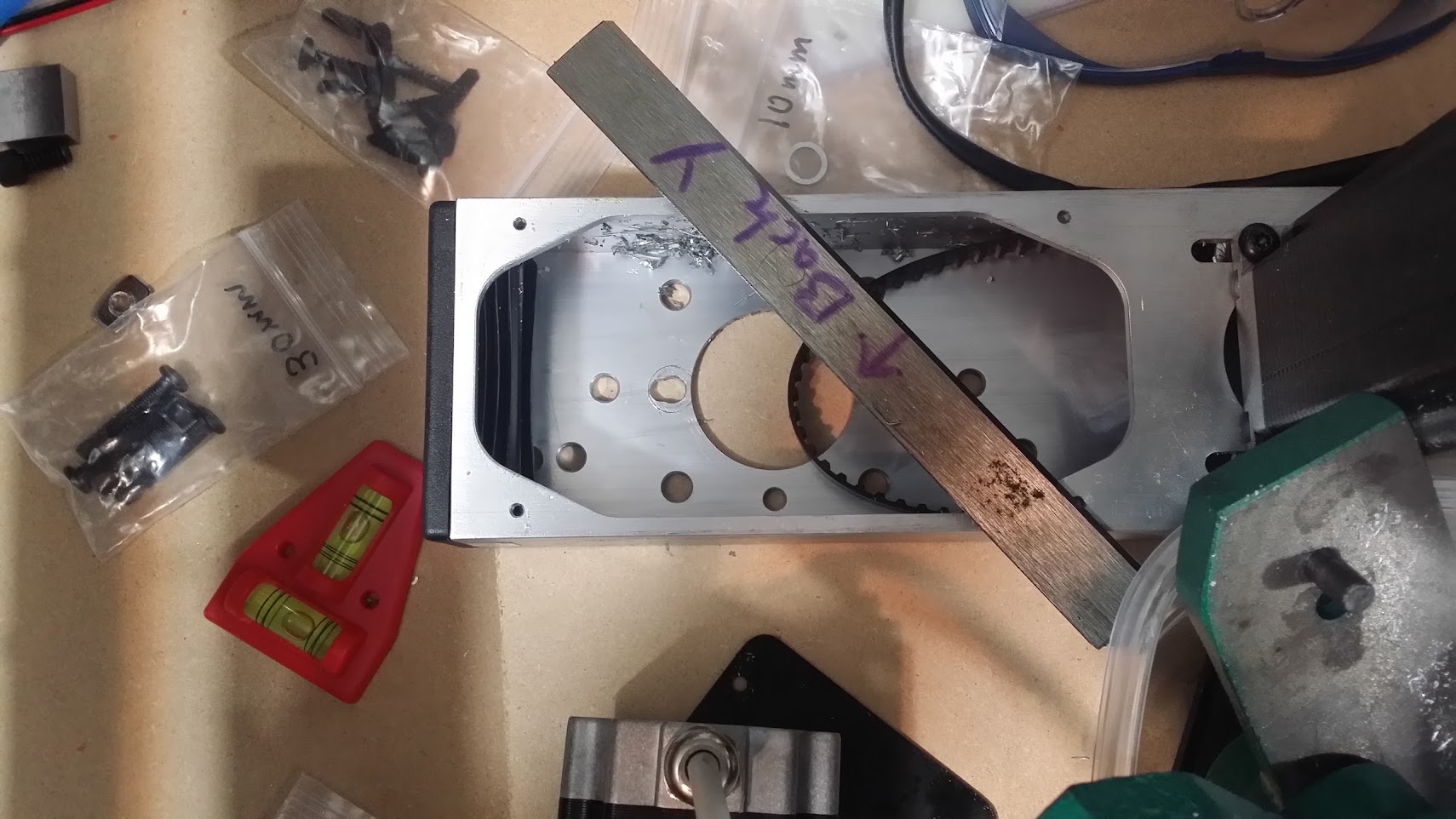
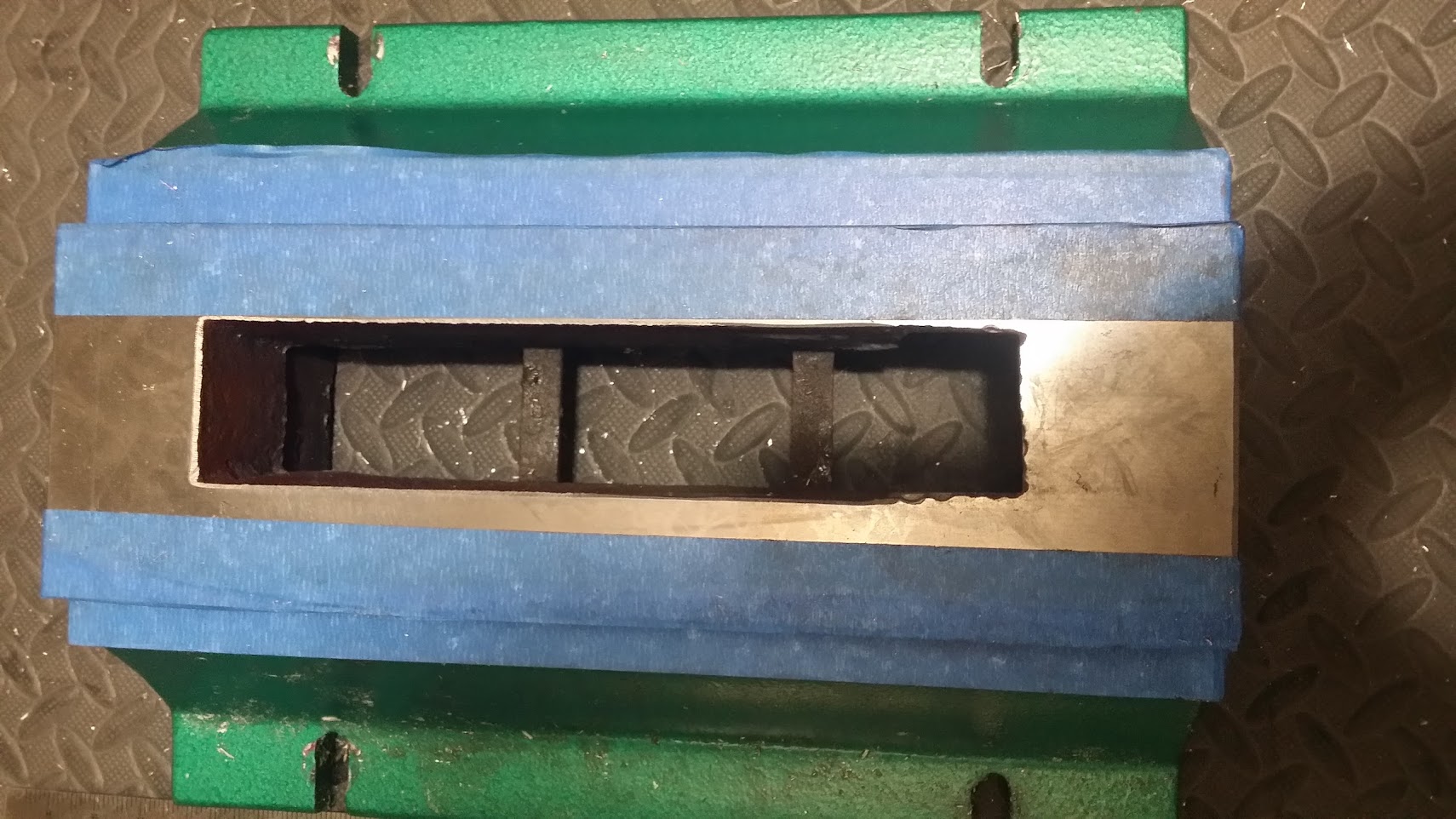
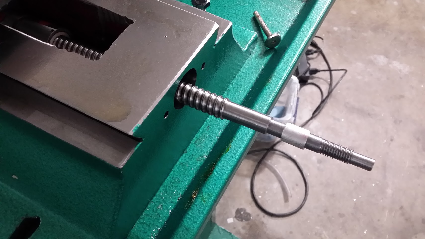
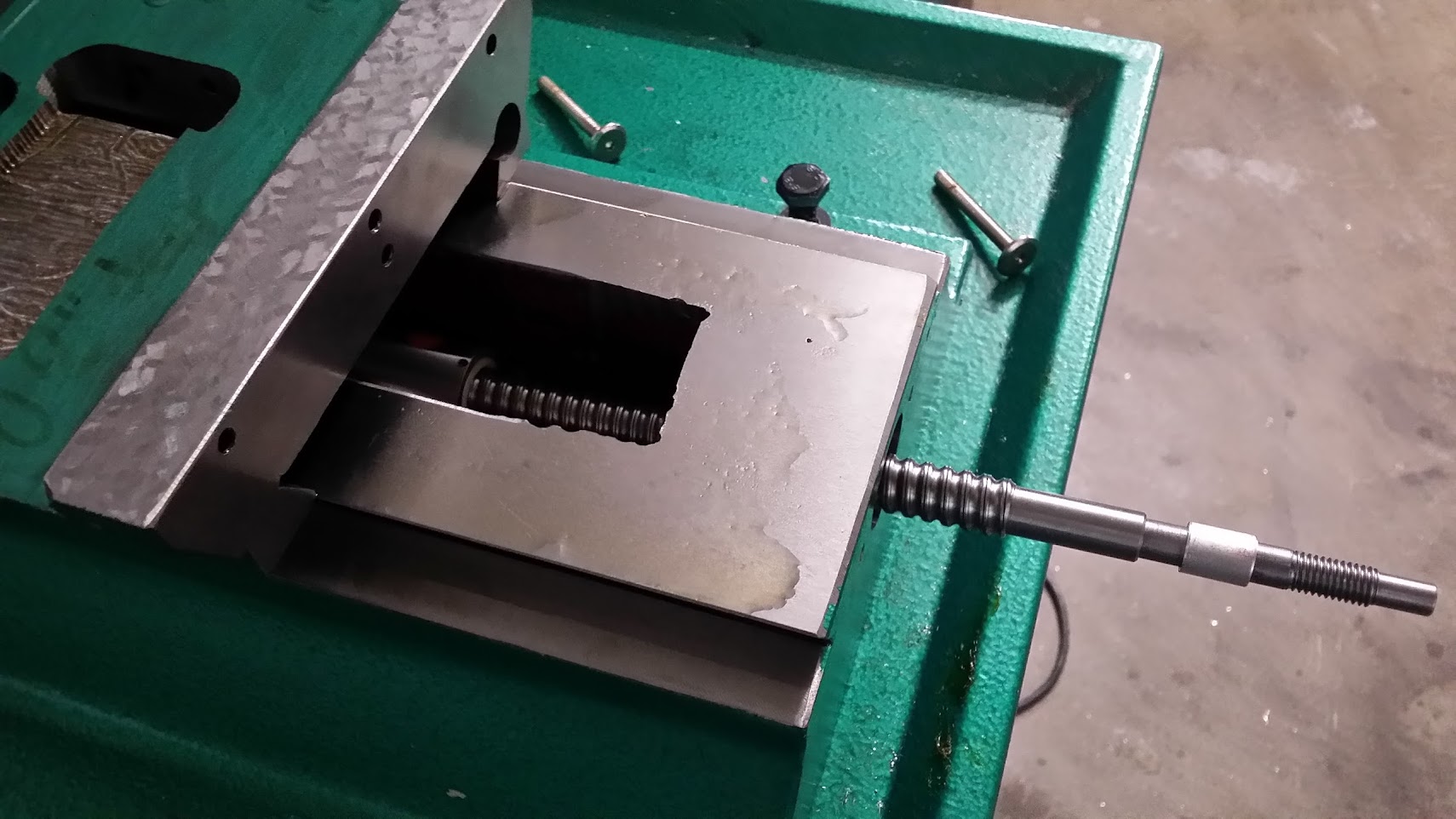
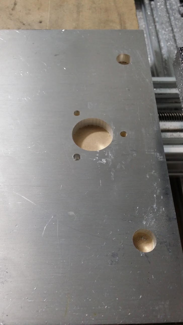
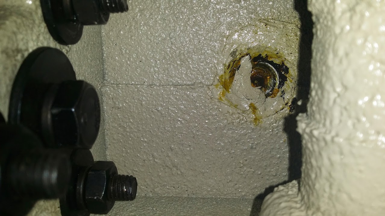
cut out a 2.5" section of the casting to clear the ball nut, a lesson here is don't believe what you see other people do on the internet, even if their video editing skills are amazing, coz that means they're great at videos not necessarily measuring/etc. it ended up a lot more than we needed, but that is ok. I used the drill press with an end mill/drill and cut it out then hand filed it a bit.
also drilled out a larger and slightly wrong offset hole, used a step drill and a dremel to get this out, very dirty wear a mask, gloves and eyewear.
added a spacer to the ballscrew since we're now getting much more Y travel.
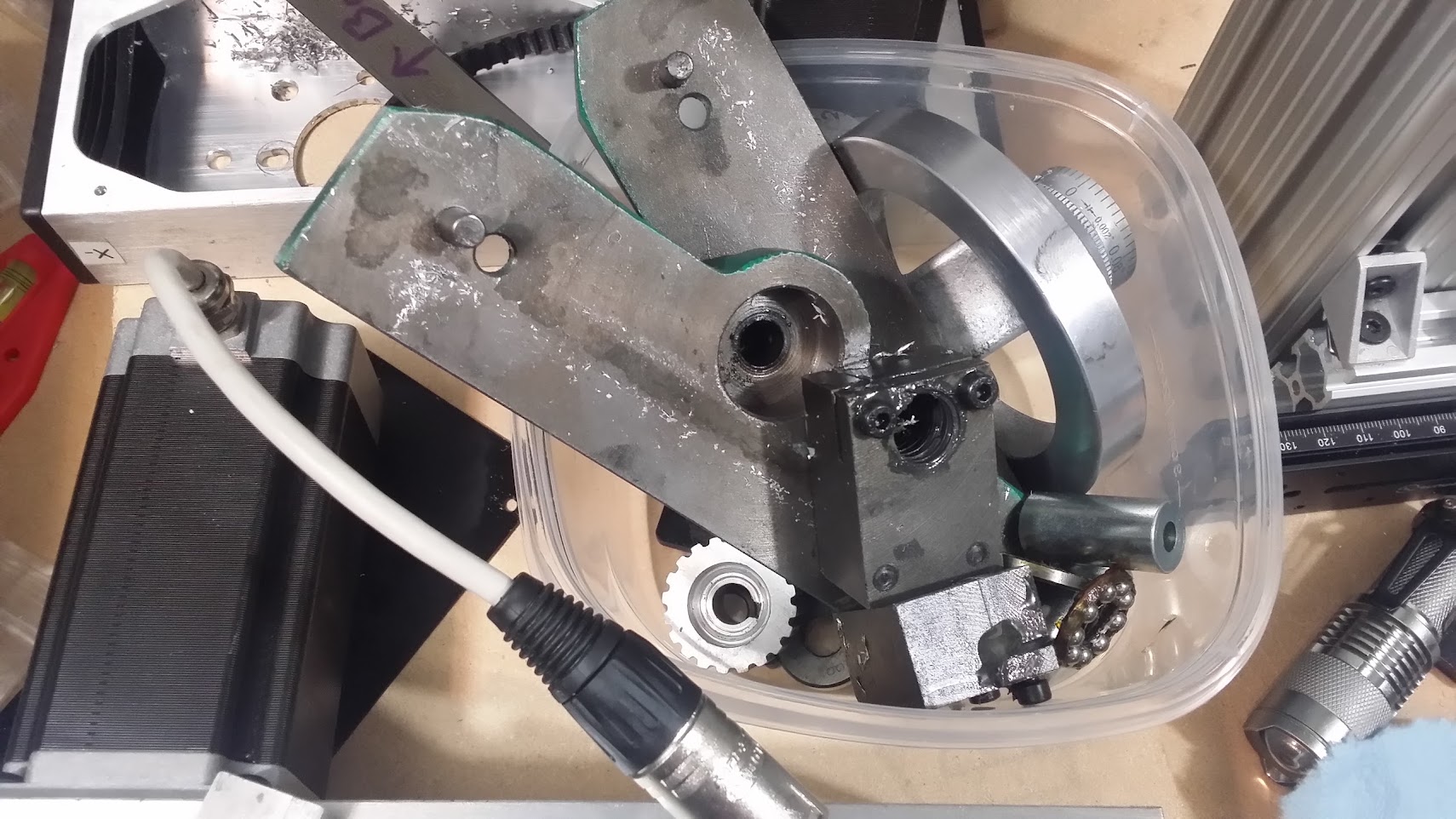
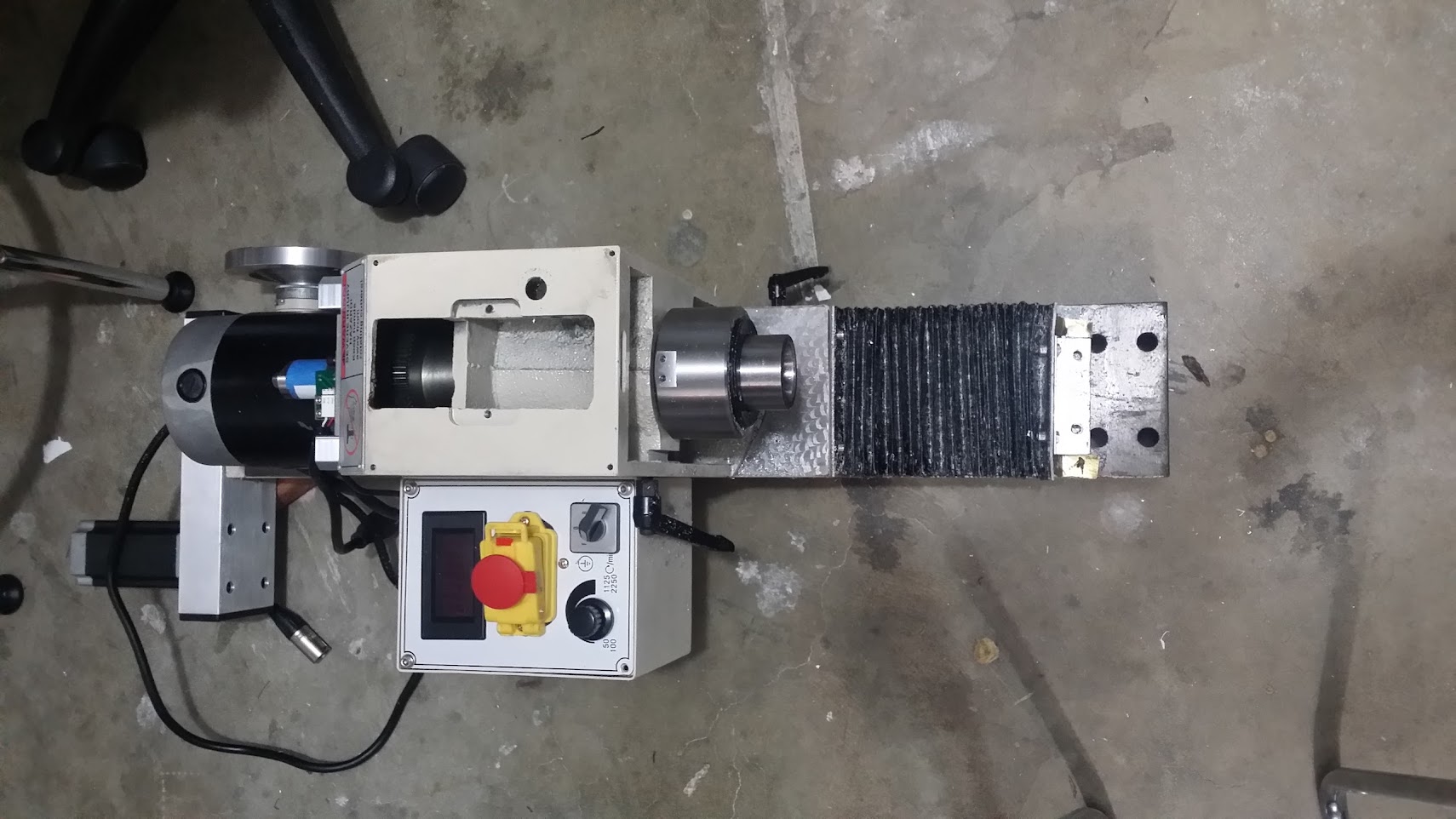
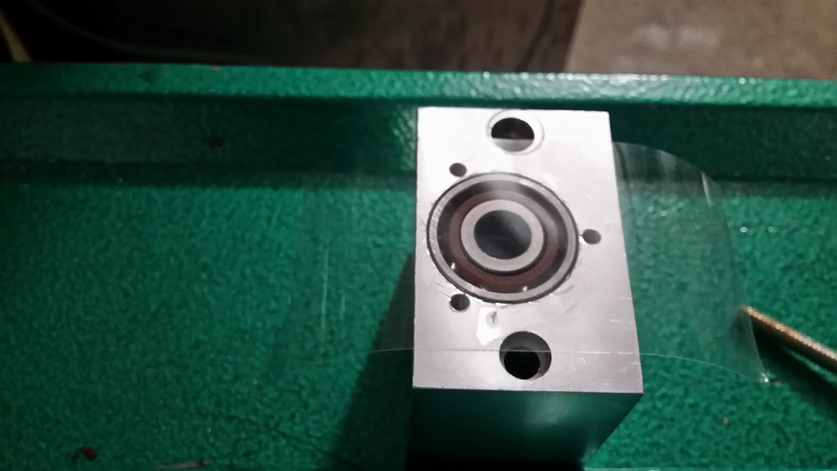
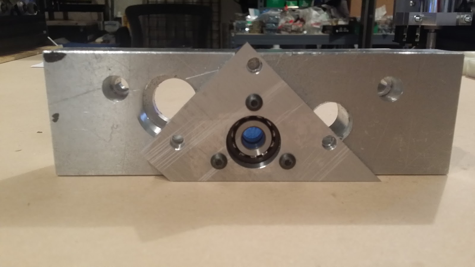
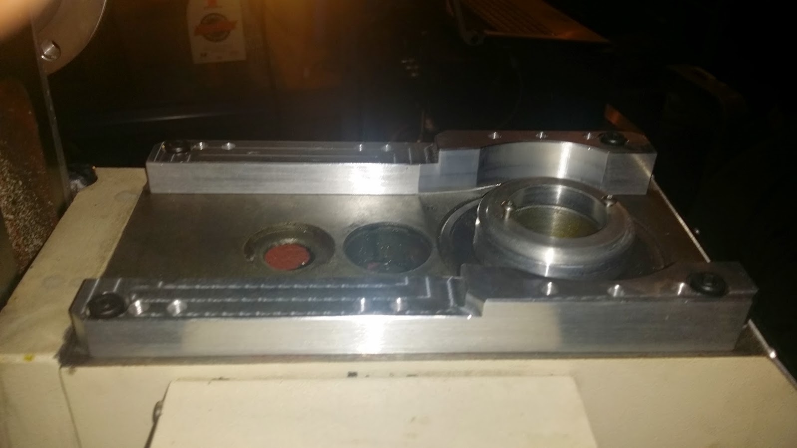
the Y bearing mount
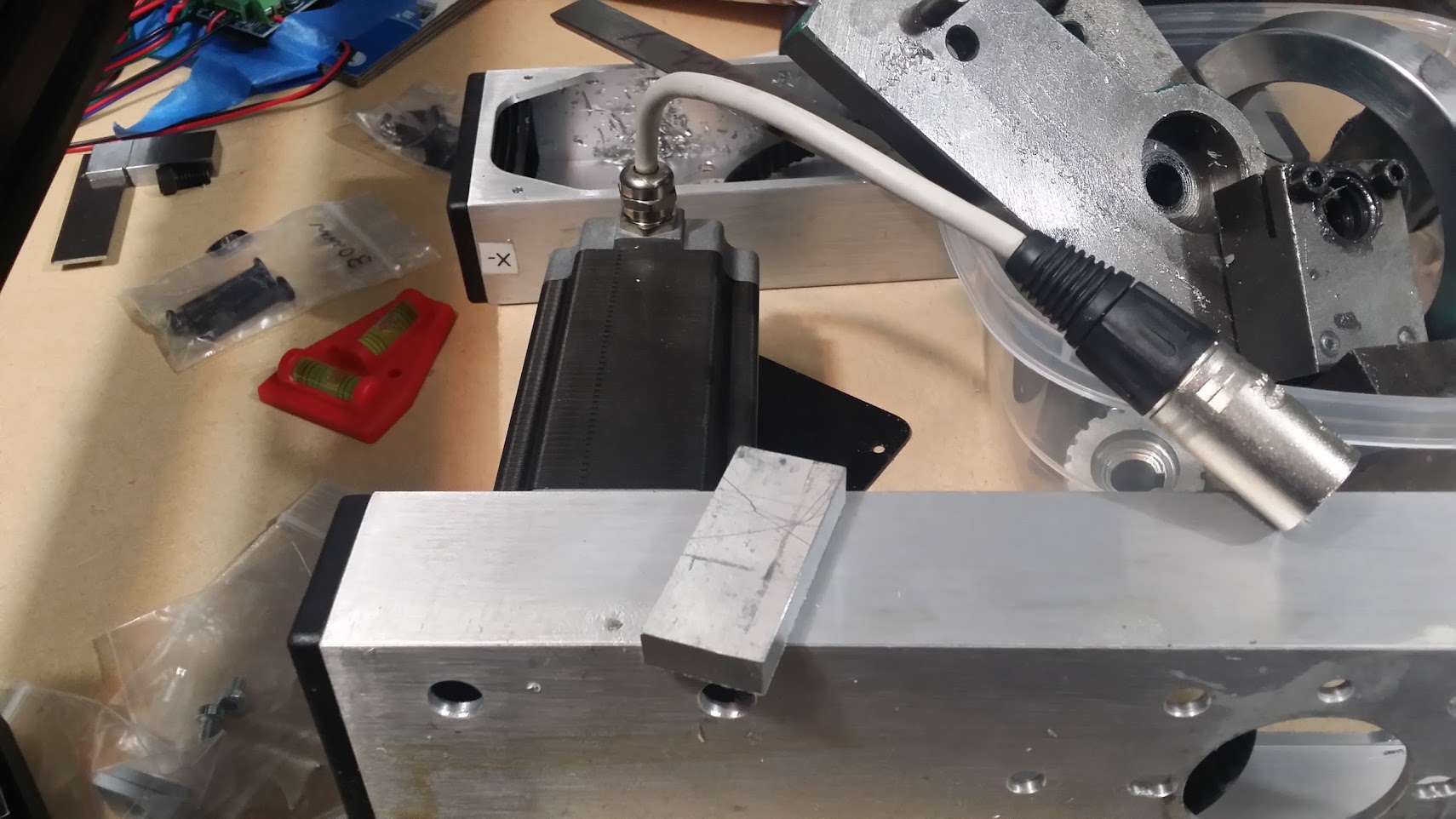
next step put all this stuff back on.
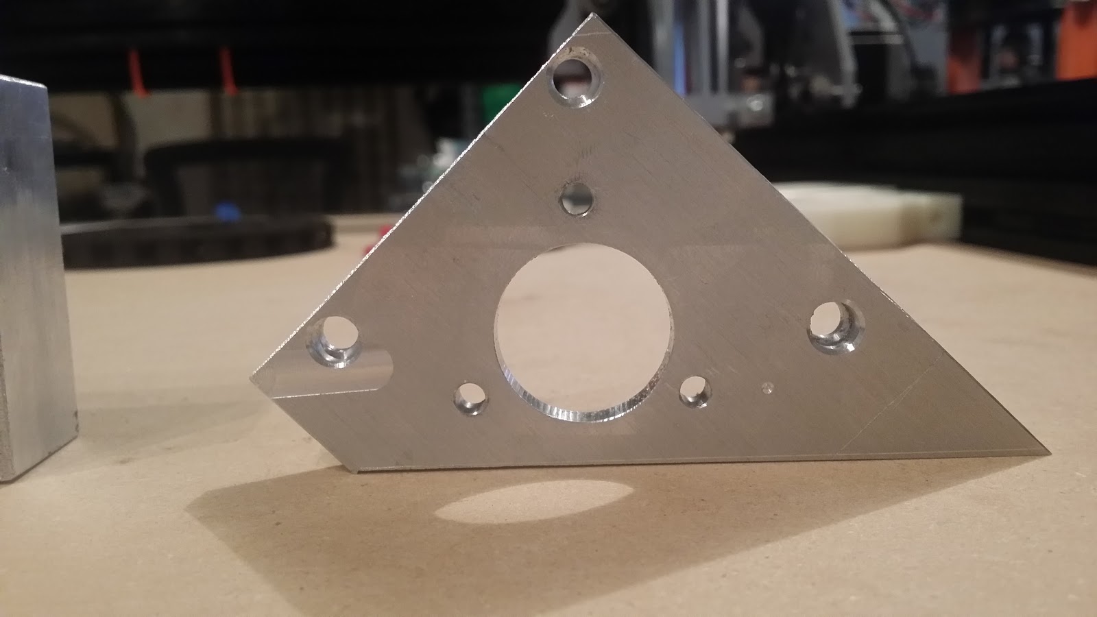
new plates made on the C-Bema
these go over the x plate, then the existing aluminum extrusions from flashcut get mounted onto that. I'll share the CAD drawings once we've verified.
i'll put together some more pictures and better instructions, this was one of those heavy build focused weekends, so didn't document a lot again.
-
Waiting for IMS to open...
07/25/2015 at 14:35 • 0 commentsAngle stock didn't turn up from speedy metals yet, inorite? So i ordered some at IMS last night and they'll have it in will call today. Now i'll have more 3/8" 2.5"/2.5" angle than i'll know what to do with.
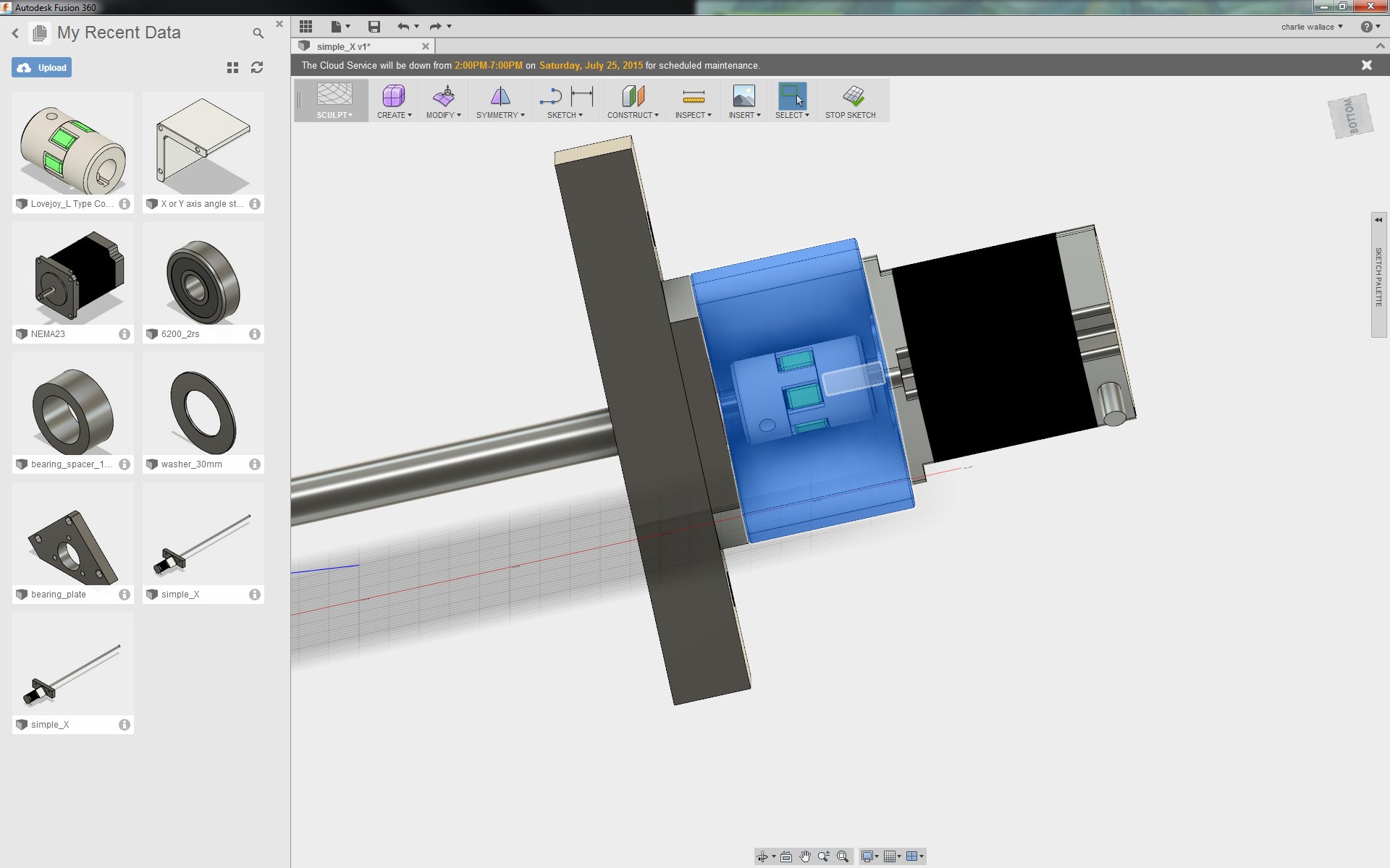
The highlighted part is what it is for, I'm liking fusion360 (full disclosure I work with autodesk but that wouldn't make me use it if it was bad) so far, it's nice and easy to use, NYCNC has a few tutorials up.
![]()
Maybe we'll actually get a ballscrew mounted today.
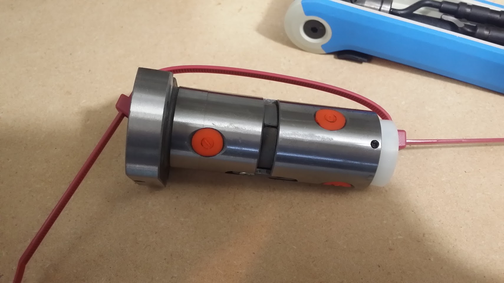
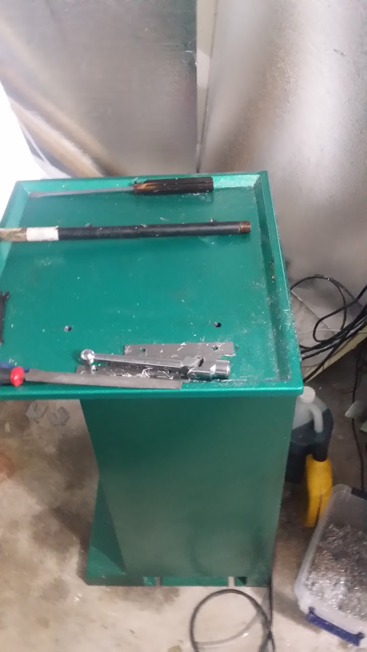
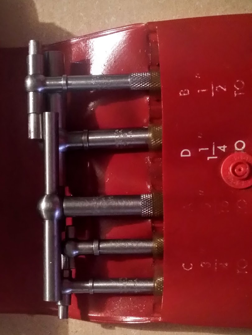
Grabbed some neat tools from fleabay, they're used to measure holes accurately, which is a lot harder than i thought it'd be.
you loosen the top, the T part is spring loaded , insert them into the hole let them settle and tighten the thumb screw at the end and they lock in place , then remove them at an angle and measure with a micrometer or caliper. very neat, single use tools are awesome. measuring things is an art form in itself
OK and i've sucessfully used up enough time i can head to IMS and it should be open
Got there at 7:59 and there's already a queue!
Luckily, ingress portal.
But i'm on will call, so walk around the side and i'm the only one there, first customer of the day.
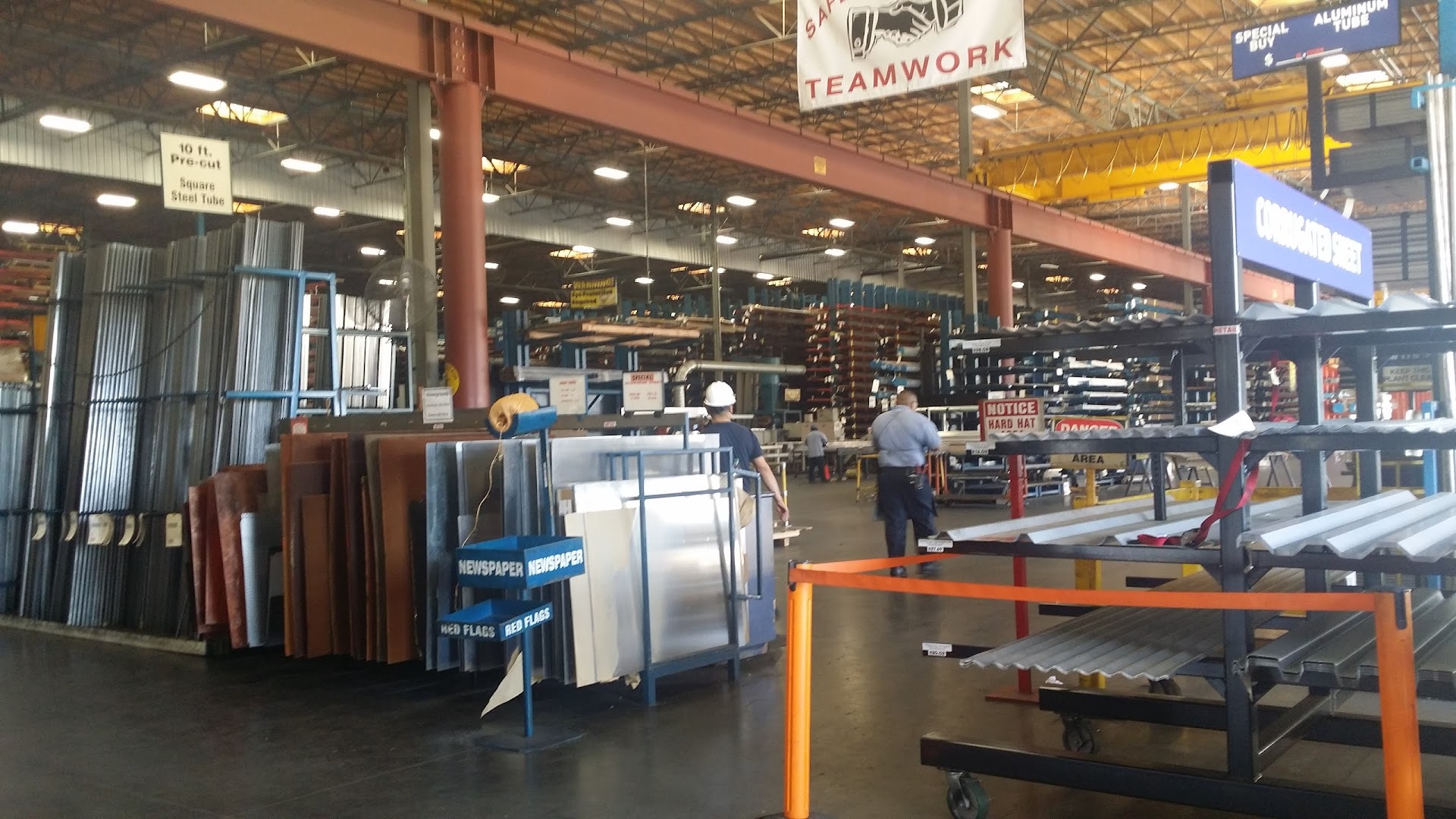
It's the costco of metal.
Mission accomplished.
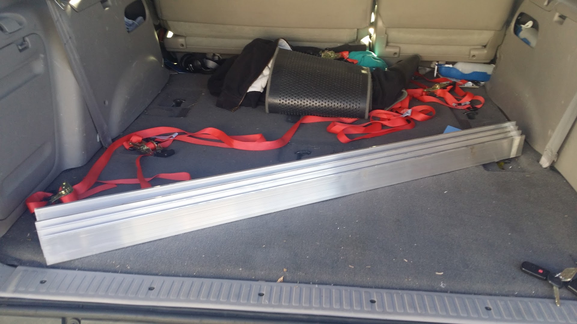
And home by 8:30, time for coffee before getting ready to bandsaw up into smaller sections, i only need, three pieces of this about 2" long, but i'll likely never run out of it.
-
just some pics/videos of part making
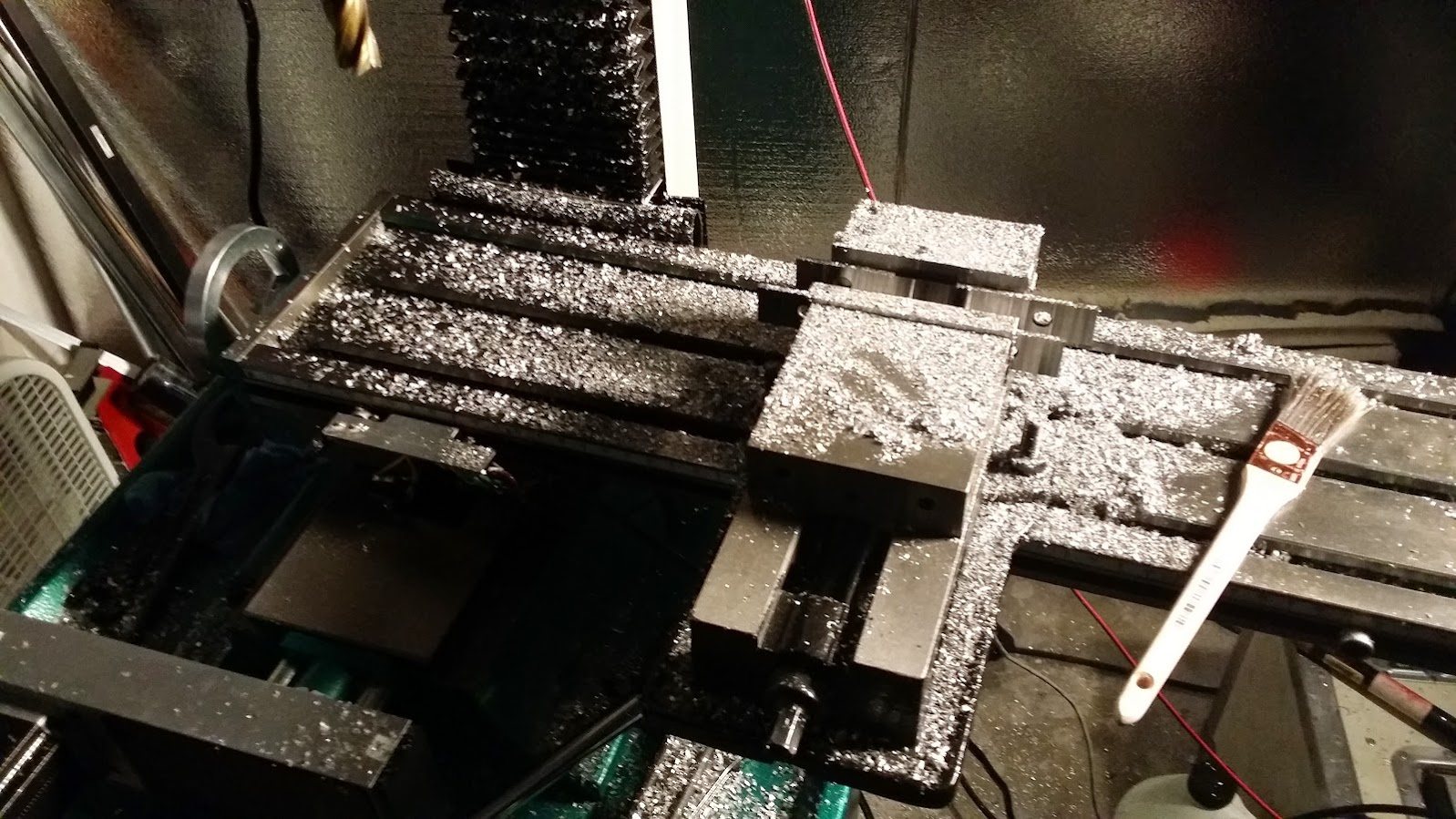
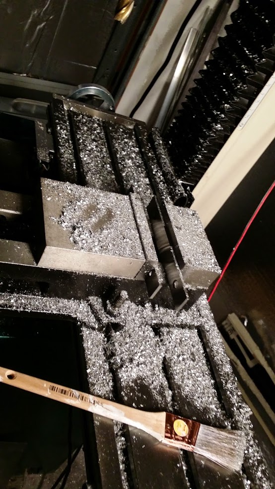
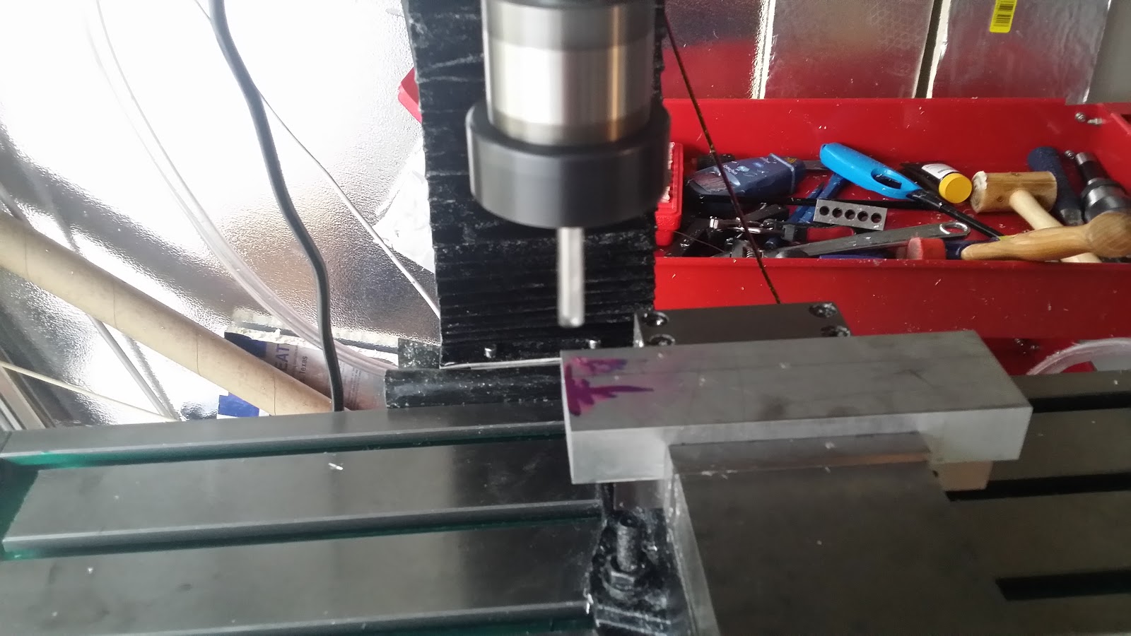
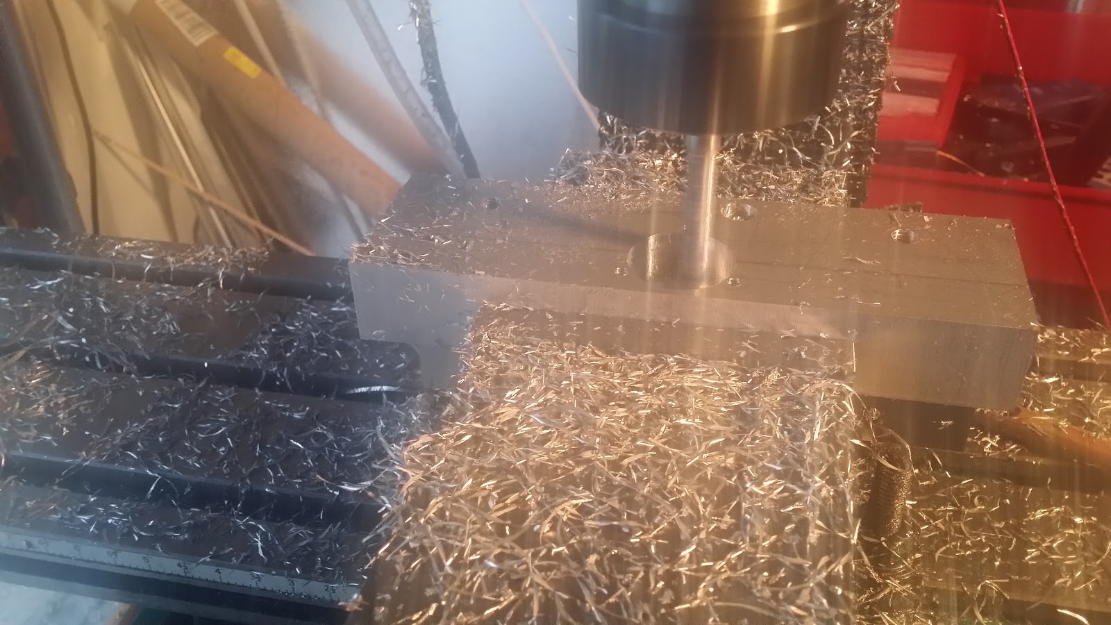
07/20/2015 at 15:48 • 0 commentssetting up to make a the X bearing plate for the ball screws... of note its important to match your tool libraries between cad and cam software, see that endmill ?
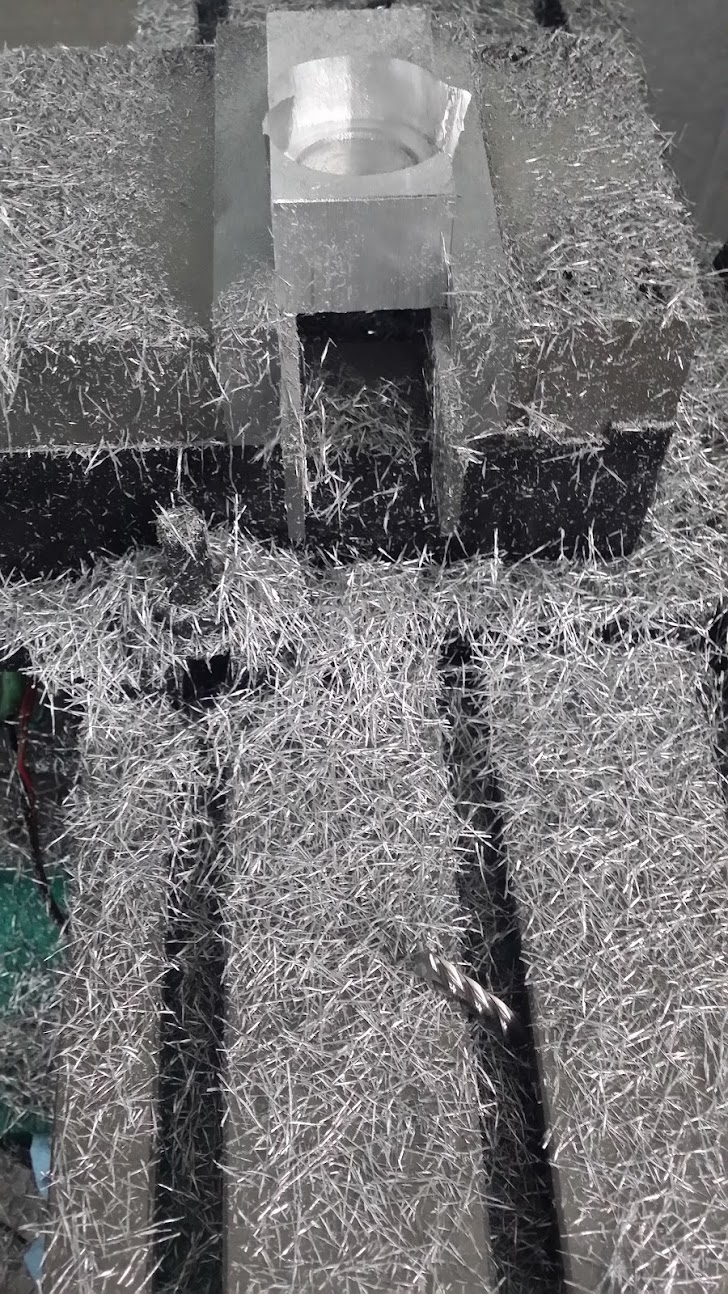
because otherwise you might do this
i printed out a sheet of tools and speeds after that.
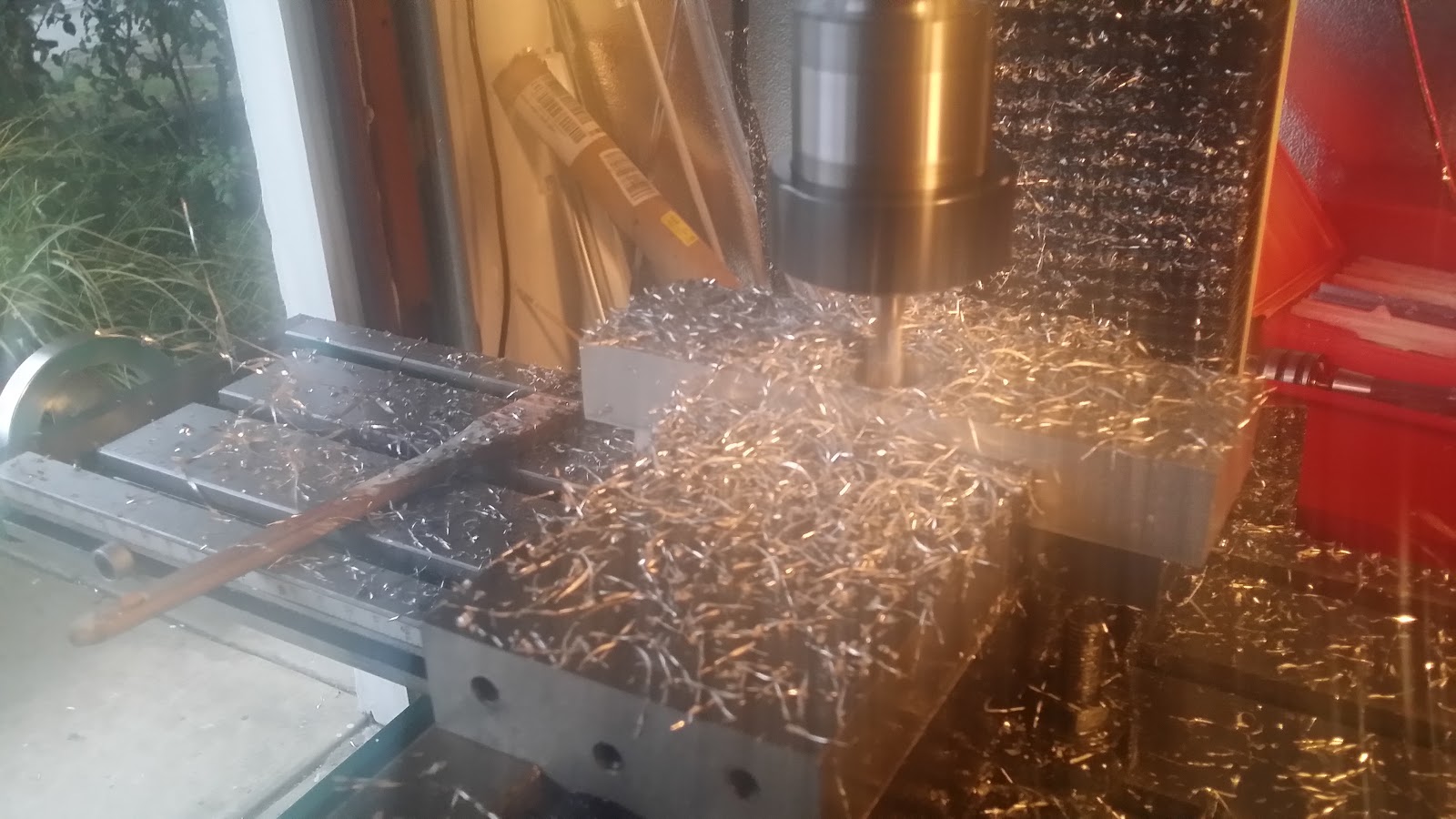
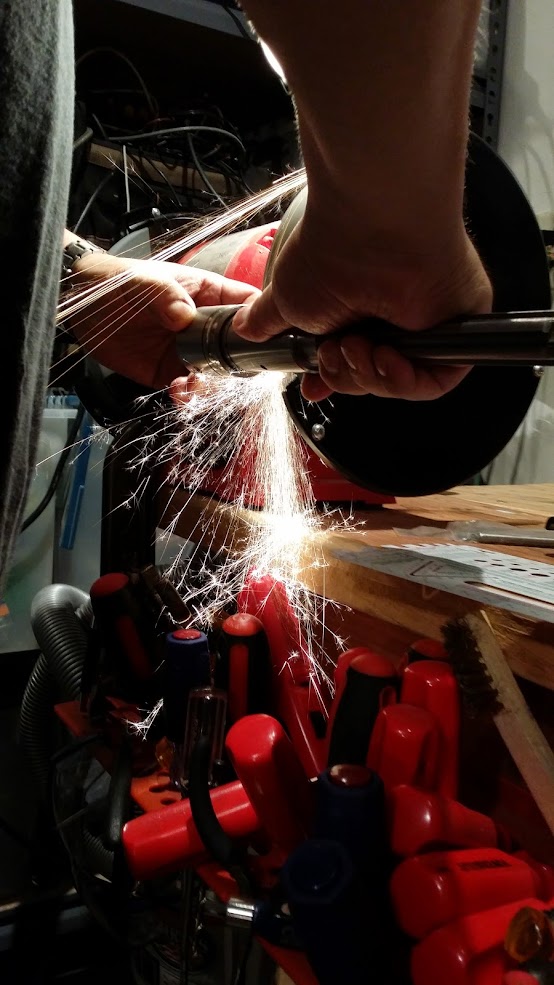
not entirely sure why the camera got all sparkly like, didn't realise the humidity was that bad.
drilling
milling
before the spring pass
spring pass starting
spring pass
the hole was still slightly undersized though.
-
G0704 ballscrew conversion.
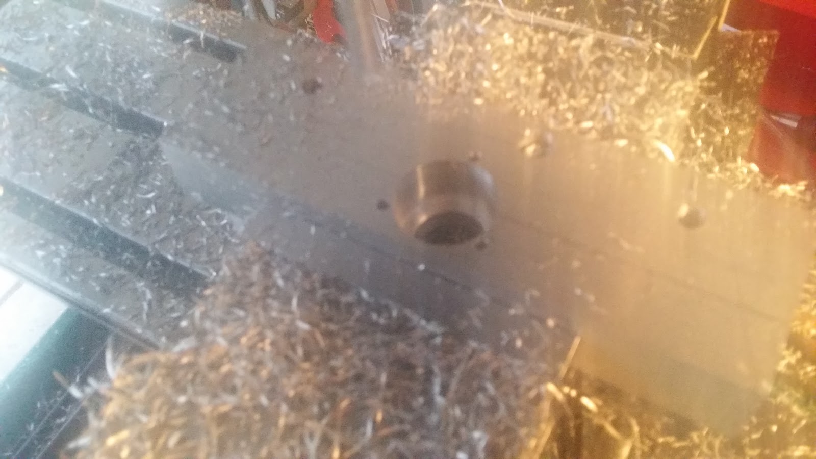
07/19/2015 at 23:12 • 0 commentsOften in machining and similar projects you make a temporary part, or machine to make a machine. With the G0704 we're trying to cut a circle for a bearing that is part of the mount for some C7 ballscrews, which ironically will improve the backlash which causes the issues with cutting circles in the first place.
So after designing a plate, and machining it out the bearing wouldn't fit so we took two approaches, measure the backlash and do software compensation, pick up a boring head and finish a circle with it.
We did both,
so far it looks like this, it ain't pretty but it should work all it has to do is hold up long enough to re-run the part on the new ball screws and then it'll be all nice.
this one wasn't paying attention to raising the Z and i only had jobber length bit it tripped the Z limit as it was also moving X/Y so ended up slightly off. But after measuring the backlash and softwaring it out , it was cutting a circle.
the inner circle on this one has a spring pass, running the same GCODE again to account for spring in the cutting tool as it removes a lot of material the bit wobbles a little bit, so running it again where its barely removing anything causes less deflection of the bit and then finish is nicer. The CAM software can do this automatically as a finishing pass.,The previous doesn't.
-
bearings, again
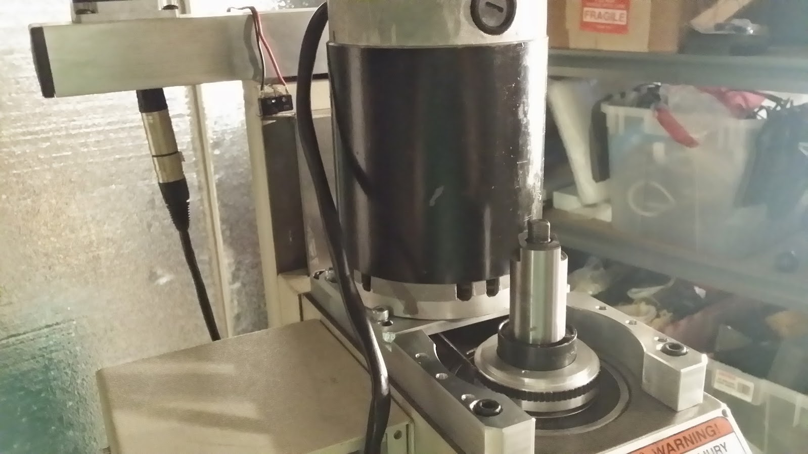
04/26/2015 at 20:02 • 0 commentsSo we searched on the ol'e internet for people that had installed the spindle bearings and couldn't find one example that'd shown all the steps and so we ended up trial and error and last week after we thought aha its all good, and ran it , realised that the spaces on the top bearing for the spindle were blinding obviously not meant to go underneath but on top.
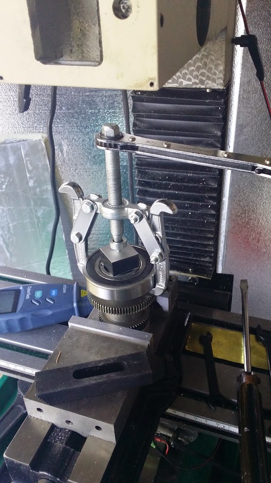
so pulled it off again. This time i opted for a two part pulley puller, which was a lot easier to handle.
![]()
http://www.harborfreight.com/automotive-pulley-puller-66868.html
flip the jaws around, and it'll let you grab the lower bearing (or the spacers) and then pull it out.
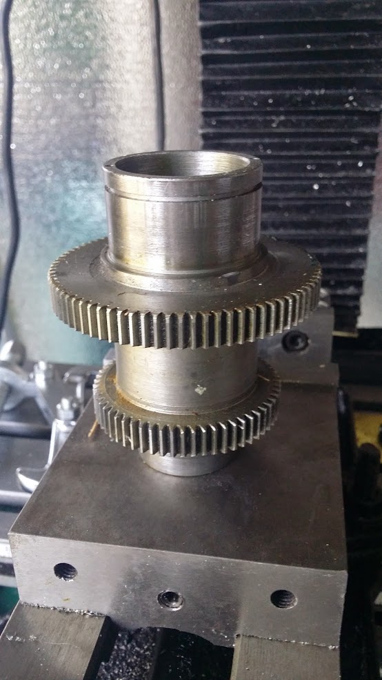
of course getting the lower bearing out again meant popping the bearing, which leaves the race inside, removed it with again.. used the bearing separator and a dead blow to gentle remove the race from the spindle.
used this bearing separator kit and the larger of the two to remove the lower bearing race from the spindle. put the flat side against the spindle and the angled side into the race, tighten it down til it starts to move and you can get purchase on it, then flip it over so the flat side is on the race and gently tap around it with a dead blow to move the race off, take your time and don't let the separator contact the surface of the spindle where it mates with the bearings.
![]()
http://www.harborfreight.com/bearing-separator-and-puller-set-93980.html
we are now experts at removing bearing races ;), last week i marred the spindle a tad and we used some diamond laps to clean it up.
so lower bearing, 4 x 1mm of the spacers on top of the bearing, so it mates with the outer housing. then however many you need to be able to lock down the top bearing, the spacers go on top of the bearing again.
the giveaway that it wasn't right was that the R8 slotting screw was centered in the hole now, even though it should have been obvious when we installed it, but paid so much attention to trying to finding someone else who'd done it and documented it wholly, and then measuring up the inside/outsides etc didn't think about what would happen with the upper bearings spacers being underneath when the machine pulled down... ah well..
so its back together now, and this coupled with the belt drive have vastly improved the finish quality of the test facing we did, the interference patterns are considerably less noticeable.
next is CAD'ing up a Z axis holder for a nema 23 to direct drive (or maybe we'll go belt) and mount the Z ball screw since its the easiest, i'm learning more of solidworks to do this and we'll measure up the machine, i'm going to remove the upper plate and CAD a new plate with a standoff to hole the motor for the DD, replacing the not so great flashcutcnc boxes one axis at a time.
but at least i'm not using eagle to do my cad now ;)
-
Bearings installed, supercharged lotus elises, and superglued fingers.
04/19/2015 at 02:45 • 1 commentReplacement bearing installed, picked up some plastic and copper tubing, cut it down and faced it. Then used that to install the bearings. Someone also came by with their TVS elise to have their lotus ECU reflashed (no good deed goes unpunished), so that was an interesting break since the laptop i use to run the CNC had developed a problem where when it was switched on, it wouldn't turn on again without a reflow of the GPU, but it was all setup to reflash the ECU, so i took it outside flashed the car and then as we were talking and saying goodbyes i closed the lid on the laptop.. nooooes.. and sure enough it wouldn't boot up again.. Stuck it in the refrigerator for a while and got it back online. the later i had to superglue the top of finger back together.. so these are all reasons for again poor documentation.
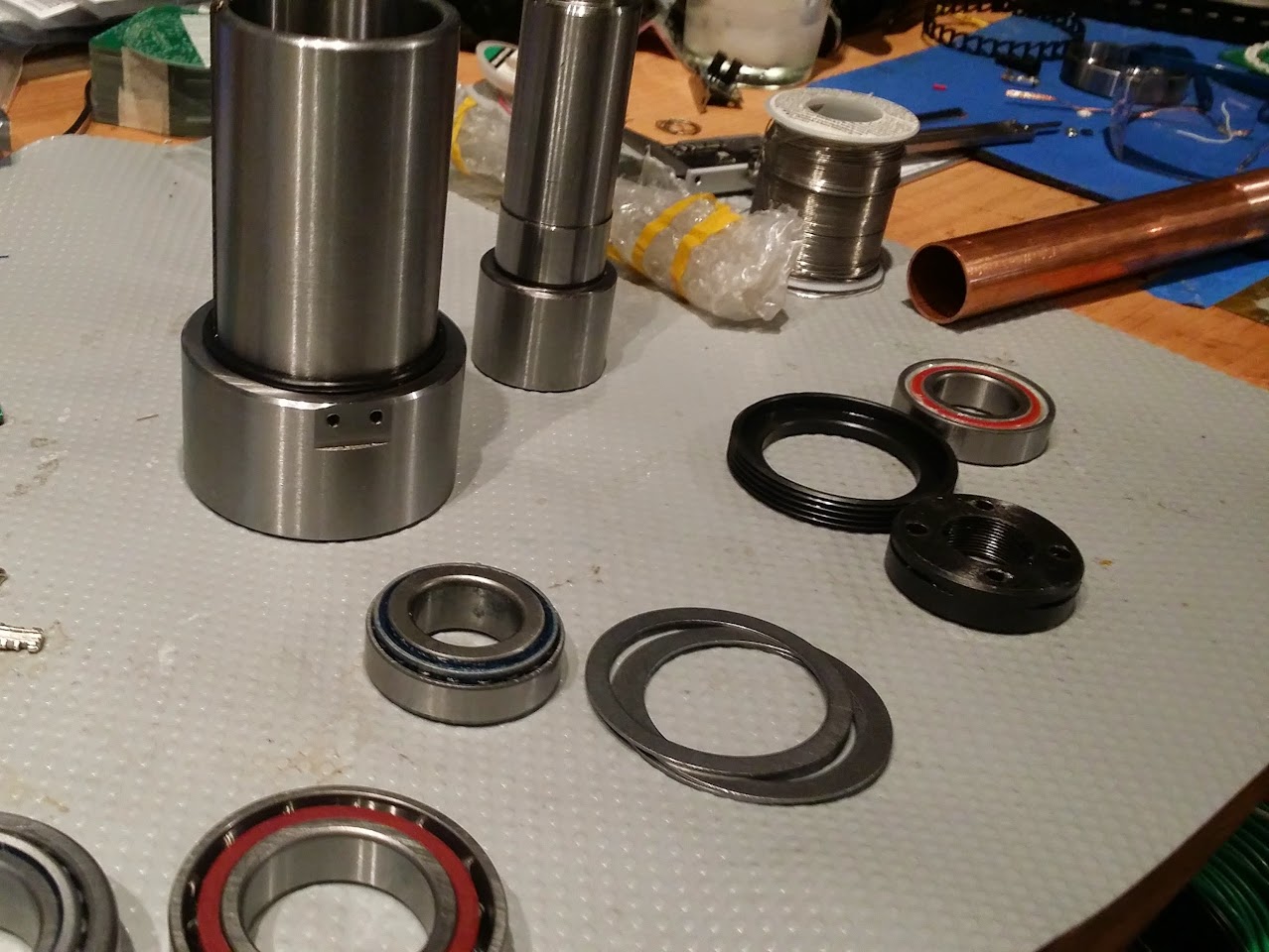
The various bearings left over, old and new.
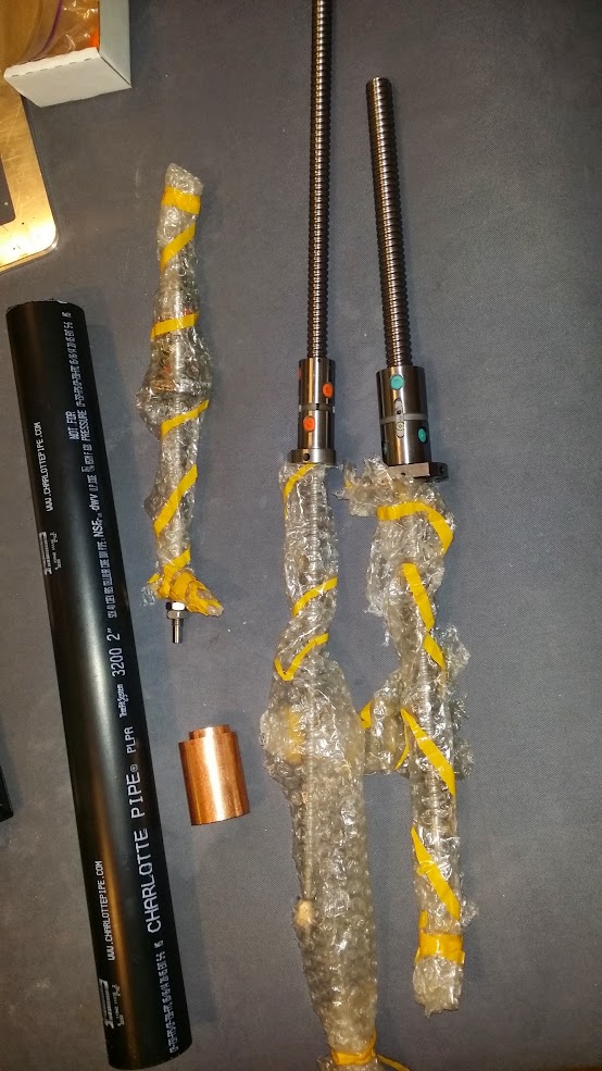
various tubes ( and next stage which is the ballscrew update). the tubes are used to help press in the bearings without marring.l
![]()
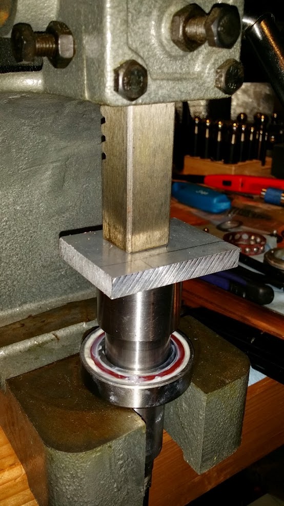
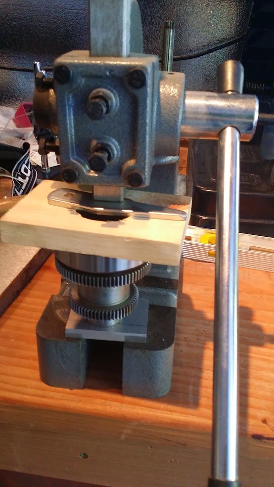
pressing in the bearings, we used three 1mm shims on top of large bearing, and two 1mm plus one as a washer on the top bearing.
![]()
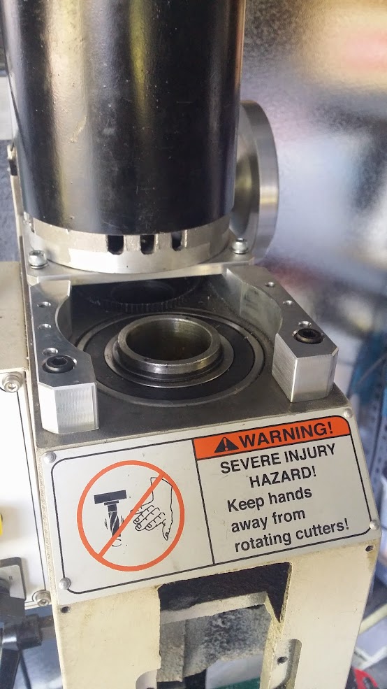
jig to mount the bearing into the spindle( piece of my neighbours wall)
![]()
I'll add more details later. when the googles has uploaded all the videos.
-
Changing out the bearings.
04/12/2015 at 16:50 • 0 commentsTime to change out the 4 main bearings on the spindle. There are lots of videos on these, but so far i've yet to see a complete one. They all go from here's the mil, til here's something then its done. We're got to a point where we were left scratching our heads a bit on the last step , which we still haven't solved...
Videos to watch
interesting formatting on the videos, first one if you use the button above, wide ones are if you press enter with the url
I have face spanners/wrenches and OTC toyota CAM removal tools, it did come in handy later but a face spanner that fits is useful, we just used two drill bits that fit in the holes and turned them.
Hoss seems to have some magical cnc that all the bearings are hand tightened, i'm guessing he removed them a few times.
I used the bearings that did about 10,00 RPM
Top bearing
![]()
Spend some time watching videos from hossmachine and russtuff, then ask yourself hey what about those two bearing you never covered.
Small rig to pull the old bearing off the outer ( all the videos cover removal ) this just happens to be using the first thing we attempted to cut as a hemisphere and the gcode had a mistake, but as with all things you find a use for it in unexpected ways.
So I have loads of pulley pullers around for the car work, this is the cheaper HF 3 set, since we don't really care about the old bearing this gets it off nicely
![]()
To pull the inner bearings i flipped the hooks of the pulley puller to point outwards and then lever the, up slowly.
removed
![]()
re-install
![]() Used this cutout to push it down.
Used this cutout to push it down.![]()
The spindle bearing is a pita, we had the whole thing ready to finish and the last bearing just didn't make sense on how to get back in, since they're directional and if you knock them in one direction, it pops the bearings out, we ended up getting the bearing slightly at an angle and it took a while to get off, since there is no lip to grab on the new bearings, it is really difficult to remove . So we ground off two flats and got it off that way.
![]()
Taking photos you notice things like the gas lighter under the grinder, so yeah moved that :)
This is the first time we've gotten to where we couldn't get it back up and running in one day, since we trashed the lower bearing its just not worth taking a risk if a bearing feels wrong, it likely is so i just ordered a new one and we'll try to finish it up next week, and again try to take more pictures.
LayerOne is coming up soon, so some of the day was spent debugging and testing the new badge prototypes.
Bearings I used.
VXB
6209ZZE Nachi Bearing Shielded C3 Japan 45x85x19 Ball Bearings ( 1)
6007ZZE Nachi Bearing Shielded C3 Japan 35x62x14 Ball Bearings ( 1)Bearings Direct
7005CP5 Precision 15 Degree Angular BallBearing ID 25 x OD 47 x W 12mm ABEC5 USBC/UBC 7007C USBC 7007C Precision 15 Degree Angular Ball Bearing ID 35 x OD 62 x W 14mm ABEC1 McMaster-Carr
Line Product Ordered Shipped Balance Price Total 1 98089A404 Type 18-8 Stainless Steel Round Shim, 1MM Thick, 25MM ID, 36MM OD, Packs of 10 1Pack 1 0 8.66 Per Pack
8.66 2 98055A435 Spring Steel Round Shim, 1MM Thick, 50MM ID, 62MM OD, Packs of 5 2 Packs
2 0 4.66 Per Pack
9.32 3 98055A346 Spring Steel Round Shim, 1MM Thick, 35MM ID, 45MM OD, Packs of 10 1 Pack
1 0 7.66 Per Pack
-
adjusted the RPM via the controller board.
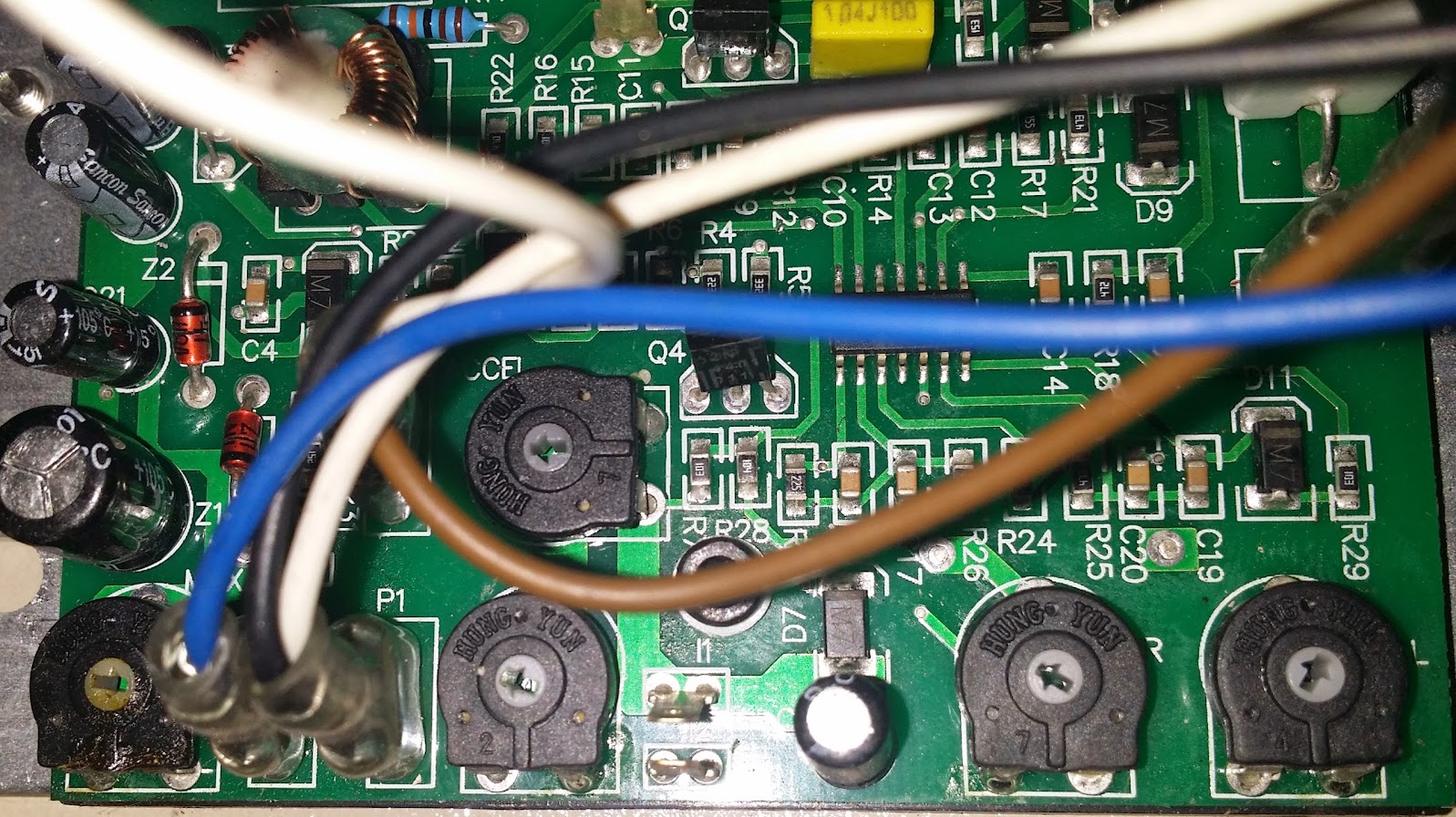
03/31/2015 at 05:03 • 0 commentsSince I was disappointed to only get 2880 RPM with the belt drive with a reduction of 0.7 I pulled out the motor controller and adjusted the pot on the bottom left marked MAX, it had about 1/8th of a turn left so i moved it 1/16 which pushed my RPM from 2880 RPM to 3200 RPM there's a torque (current limit/CL) adjust, IR Compensation
Grizzly doesn't want the motor to overheat so they say only a few minutes at the top RPM anyway.
Adjusting the MAX pot also raises the MIN speed.
As always hoss tried it first, his board is different, mines just an smd version.
-
and the reversal begins, also switching to a belt drive.
03/29/2015 at 19:06 • 0 commentsSaturday we started measuring the XY backlash after last weeks tear drop circle, and wow 0.05" and .003" ! the Chinese Factory says 0.008 to 0.003" which ain't great but its a ways away from where we are.
The Y setup on the G0704 is not great, its held only at the front and the back is left to whip around.
this is what the Y side with the flash-cut conversion (sans pulley)
![]()
We couldn't get the slop out with the pulley and its two little allen set screws, so i figure cut holes out the middle and put a couple of nuts on (M8 1.25 )
mmca bust out the HF lathe (which is a whole other thing)
![]()
after modifying the pulley
![]()
that reduced our backlash to about .009" on the Y still terrible, but can't see a way to make it better. the Y motor mount relies on holding the motor box etc with a couple of normal bearings. So at this stage, its OK and we'll just change the lead screws to double nut ball screws.
next the belt drive, unfortunately often as we do these projects , something cool happens and we're all like hey that'd make a great video and we need photos. but as usual we only recall that after its done....
![]()
top cover off.
wiring box exposed to cut one black motor wire. and remove the white from the speed controller dial, bottom white.
the other wire off the side is the "safety" interlock for the plastic guard.
![]()
motors off, its just 4 bolts, remove the wires.
![]()
you don't want to whale on this so we used the HF pulley puller which i happened to have around since i use it for supercharger pulleys etc. No pics of this stage..
Which gives us this.
![]()
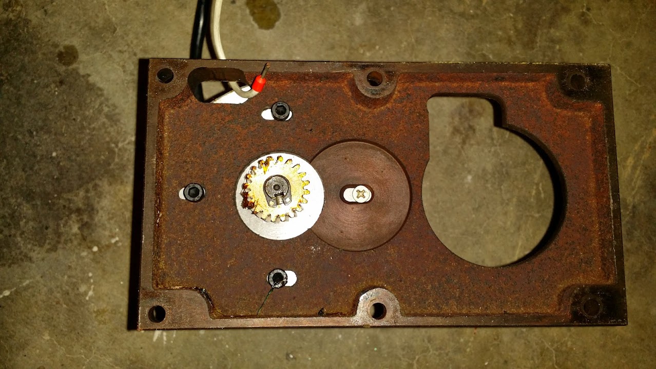
the draw bar mech needs to be removed. encoder wheel, sensor etc..
![]()
two bolts to remove the metal barrier, same for encoder. of course i did get pics of the easy stuff.
![]()
![]()
and then like 90% of the instructional things on the internet , suddenly
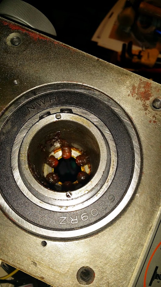
![]() spindles out, you press down the spring loaded part, i used a flat blade screwdriver then pop off the C retaining clip its not sprung its just like a thick cut washer, rotating it around a bit and you'll find the sweet spot where it'll just pop off , then easy back on the spring and lift out the round tube and spring.
spindles out, you press down the spring loaded part, i used a flat blade screwdriver then pop off the C retaining clip its not sprung its just like a thick cut washer, rotating it around a bit and you'll find the sweet spot where it'll just pop off , then easy back on the spring and lift out the round tube and spring.here's one i made earlier
![]()
at this point, replace the bearings... and remove that C spring.
![]()
for sake of argument, lets say we did that.
pull the front off, four bolts for the plate, two screws the super duper DRO..
![]()
ZERO here means that is the name of the button. in and mm mean something other than measurements.
the up and down arrow randomly change the inaccuracy.
arko had jumped ahead and pulled the quill side off, so we pulled that gear
![]()
from here. it's easy to remove, a set screw on the quill handle , pop it off and pull the above gear out.
![]()
now the front adjustment, not sure what mmca is pointing at.
![]() same again, set screw lift out the dial, and then the gear/shaft comes out but!
same again, set screw lift out the dial, and then the gear/shaft comes out but!![]() this threaded rod needs to come out, luckily its the same sized thread as a bunch of other, so i just threaded a bolt in and pulled it out. that allows you to pull that front Z quill out.
this threaded rod needs to come out, luckily its the same sized thread as a bunch of other, so i just threaded a bolt in and pulled it out. that allows you to pull that front Z quill out.top gear off, c clip and lift off with a flat blade, its plastic and we don't care about it. at first you're like, c clips, i hate them so much wheres that special tool i bought one time, turns out these are really soft and you can just use the key-way slot to pop them off with a small screwdriver and a pair of pliers. they're not being used again.
![]()
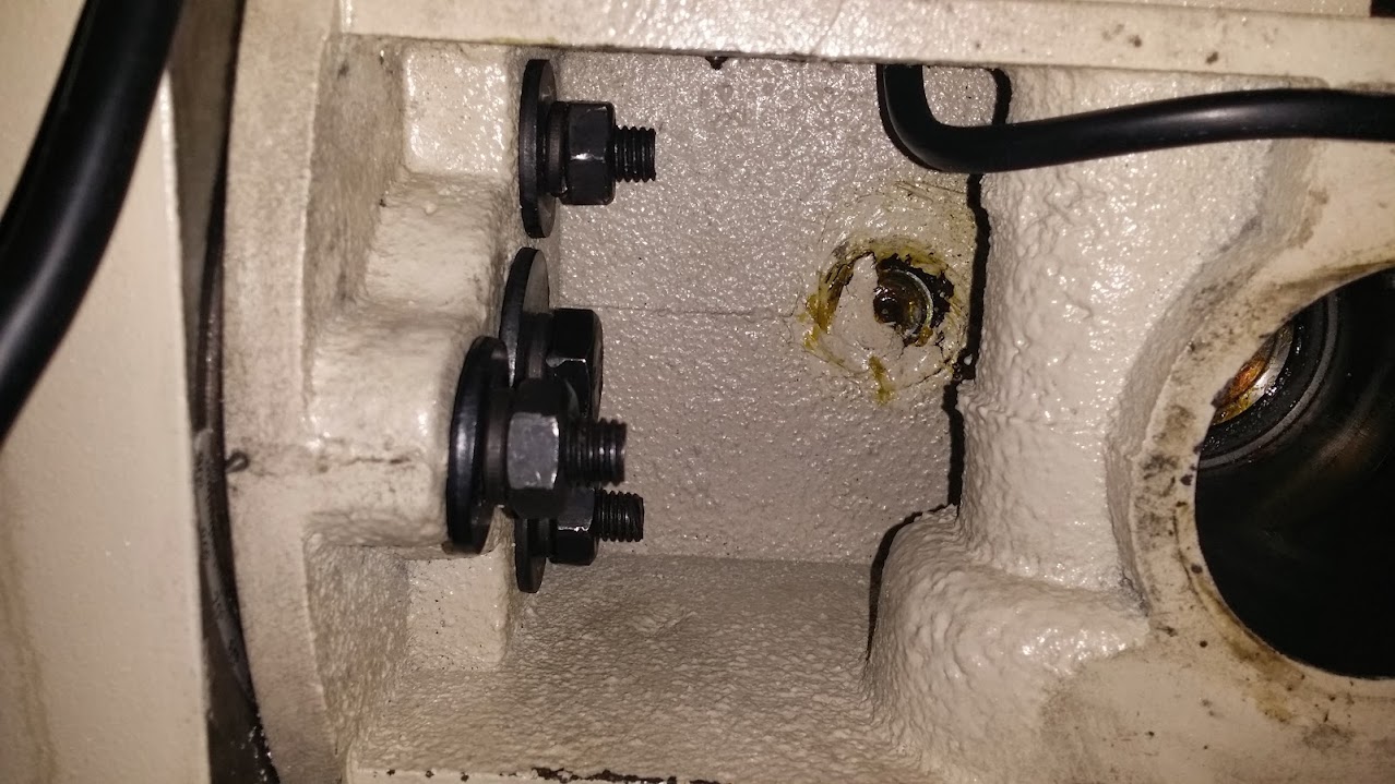
loosen the head rotation bolts. all four
![]()
rotate head thus.
![]()
we're going to tap this out with a piece of precision expensive drill rod that we're using to calibrate the spindle later..
![]()
remove this cover at the back of the head
![]()
remove the set screw at the bottom.
![]() you can then lift out the fork between the gears, it just fell off for us when the screw was out.
you can then lift out the fork between the gears, it just fell off for us when the screw was out.then you can remove the H L dial watching out for the ball bearings and detent plate, its a set screw again.
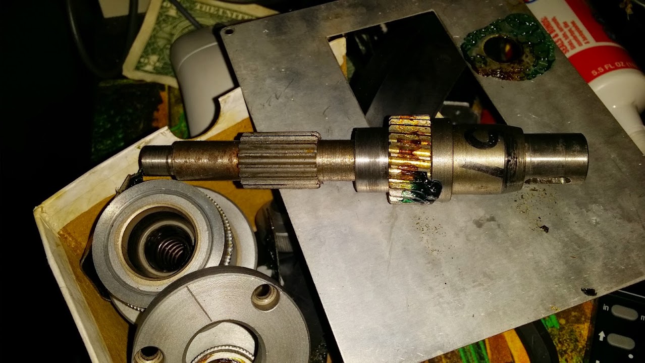
now any c clips are removed from the top of the shaft., tap the bottom side ( normal underside of the shaft when head is at 0o rotation) with the most expensive precision piece of rod you have close to your fingers, the gears will slide off with the help of the blue and green grease that is everywhere. and you can then just rotate the shaft and gears towards you and take the whole thing out through the rear cut out. .
rotate the head back and snug the bolts.
it should start to look like this
![]()
clear off the top
![]() install side mounts for motor and tap on the pulley to the spindle, fire is recommend but we gently hammered it on there with a protective piece of metal over the pulley. taking care to align the screw holes.
install side mounts for motor and tap on the pulley to the spindle, fire is recommend but we gently hammered it on there with a protective piece of metal over the pulley. taking care to align the screw holes.our screw holes were off in the kit
![]()
after test fitting the motor which as had the old gear removed with a set screw and pulley puller. then gently put the new belt pulley on there, it didn't clear the hole..... so i started to hand file it because grinding dust is exactly the kind of dust you do not want on the ways of a mill... but after about 5 minutes with a file that was too big i'd only made about 1 mm in. so time for the dremel. I covered up the machine with a drop cloth everywhere. then proceeded to grind it off.
![]()
![]()
![]() notice my use of the special blue shop towels that are inflammable.
notice my use of the special blue shop towels that are inflammable.![]() after the battery ran out on the dremel i decided that was the right amount to remove.
after the battery ran out on the dremel i decided that was the right amount to remove.and tada! , dremel engineers had exactly calculated that a fully charged battery grinding away at a g0704 would run out at precisely the right point. Thank you DE. Clean EVERYTHING after grinding, remove the drop cover really carefully.
![]()
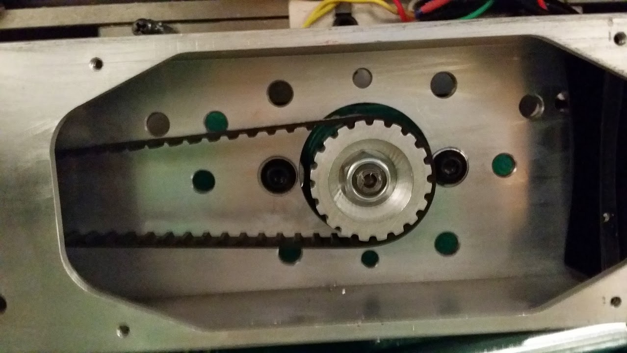
motor mounted with 60 lbs of force applied to it, to tension the belt.
now add wires back, and plug it in and it'll all work perfectly, except the sharp eyes will notice the lack of an encoder ring. more on that later.
I drilled a hole in the top of the control box to run the encoder + connector and motor wires into, this needs a grommet to stop the vibration of the machine slicing into the wire and stopping debris getting in the box where the magic smoke livs.milling
waiting for the youtubes to process that last 3 videos into one.
so its almost circular, but a lot better than it was.. .time to ditch the flashcut hardware mounts and leadscrews and install ballscrews. the feed and speed needed to be set, but it was like 2AM and no RPM and i realised the timing light i was going to use was for ignition advance, so i could tell you exactly how many degrees of retard/advance the motor was running at.
-
Tramming and cutting.
03/25/2015 at 20:59 • 0 commentsWe spent a few days tramming the mill, that involved shims ( all i had was brass sheets so ordered some stainless to replace it ) and then figuring out where all the bolts and stuff are.
mmca built a device that allows a dial gauge into the spindle and then it spins around the table, you zero out the gauge on on side, then spin it around to the other side, if its off you adjust the column forward or back with shims. then try again..
after the column we did the head trim, which is 4 bolts , loosened then rotate the hit til its square and lock it back down again. i'll add pictures and more details later..
after getting the vice parallel, we then started to cut out a hemisphere. but there was a mistake in the cam so we aborted it.... but i really like watching cnc machines at work, even if its just going around in circles.
this is .1' cut with a 1/4" HSS chinese end mill from littlemachine shop, first we got the facing working, then this.
fun stuff
![]()
![]()
maybe next i'll make one of these?
![]()
Grizzly G0704 CNC Conversion
Joining the ranks of the Chinese made Grizzy G0704/BF20 conversions.


 Used this cutout to push it down.
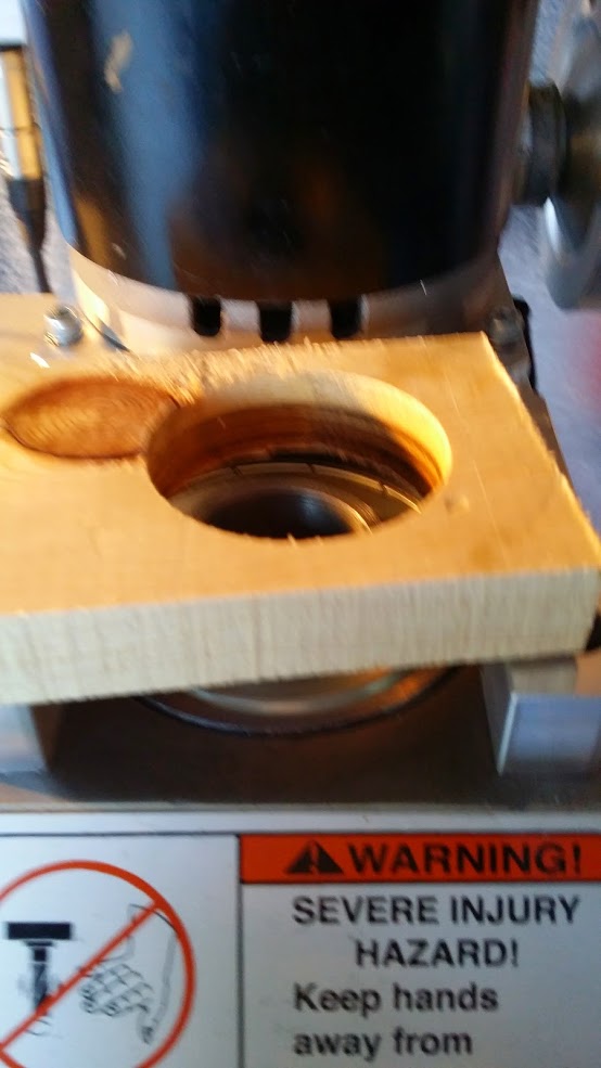


 spindles out, you press down the spring loaded part, i used a flat blade screwdriver then pop off the C retaining clip its not sprung its just like a thick cut washer, rotating it around a bit and you'll find the sweet spot where it'll just pop off , then easy back on the spring and lift out the round tube and spring.


 same again, set screw lift out the dial, and then the gear/shaft comes out but!
 this threaded rod needs to come out, luckily its the same sized thread as a bunch of other, so i just threaded a bolt in and pulled it out. that allows you to pull that front Z quill out.
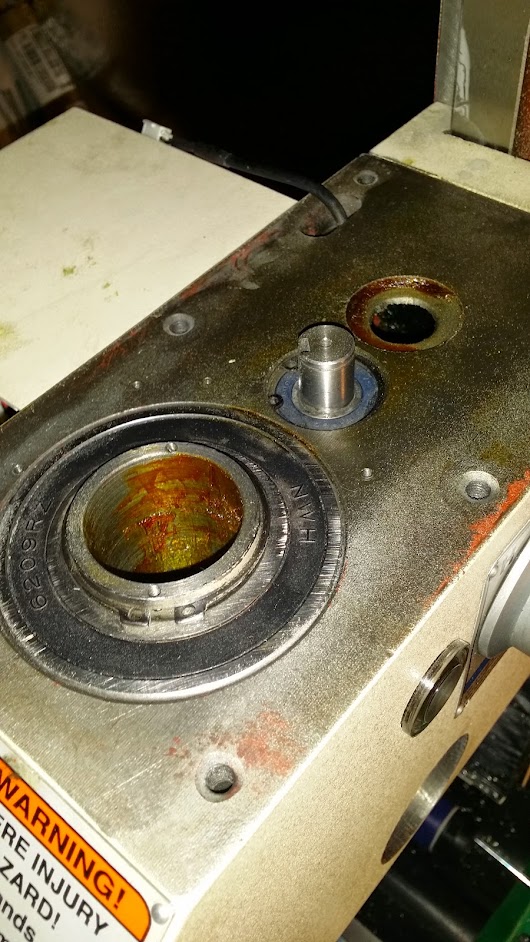


 you can then lift out the fork between the gears, it just fell off for us when the screw was out.
 install side mounts for motor and tap on the pulley to the spindle, fire is recommend but we gently hammered it on there with a protective piece of metal over the pulley. taking care to align the screw holes.


 notice my use of the special blue shop towels that are inflammable.
 after the battery ran out on the dremel i decided that was the right amount to remove.