Hello all,
There some things you will need first.
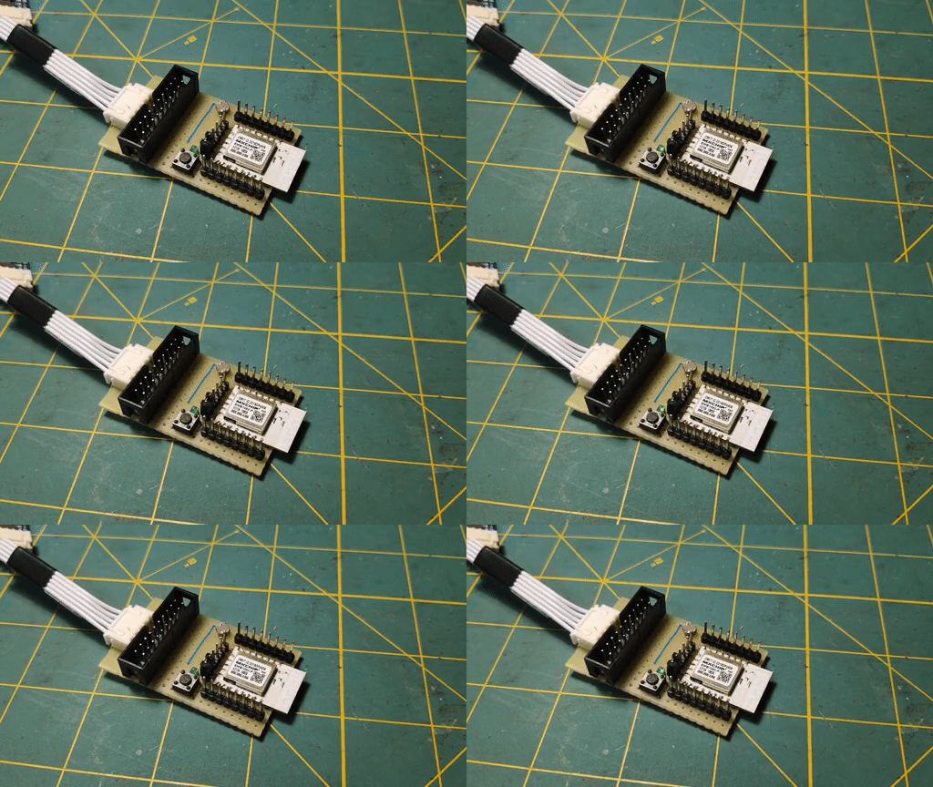
- EMB1082 module :)
- Jlink debugger of your choice. The following work just fine: Segger J-link Edu, usb-miniJTAG, J-Link OB ARM.
- Keil with ARM Compiler 5.06
- SDK from RealTek I am using SDK-v1.2.0
- Someway of powering the board, form the debugger or external power supply.
- LED and resistor
Mind you that all this information is present in the RTL8762D SDK User Guide EN pdf that you can download from realtek.
1. First make sure you have all your connections are secure and everything is powered on. My LED is connected to VDD and through a resistor to P0_0.
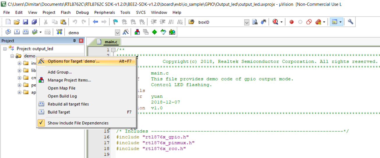
2. Next go to BEE2-SDK-v1.2.0 -> board -> evb -> io_sample -> GPIO -> Output_led and open output_led.uvprojx to start KEIL
3. In the Project section on the left, right click on "demo" and select "Options for target 'demo'".

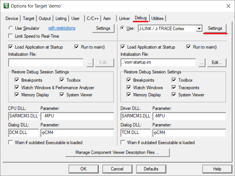
4. Navigate to Debug -> Settings

5. Next we need to change few things. We will use Port SW at 500kHz (1MHZ will also work). Connections and reset options both need to be set to Normal. If everything is correct we will se SW device listed on the right.

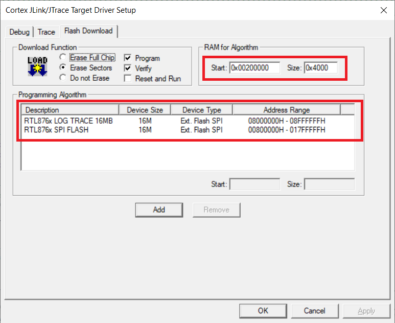
6. In the Flash Download tab we need to set the RAM algorithm start and and size values and add the algorithms themselves.

RTL876x_LOG_TRACE_16MB.FLM and RTL876x_SPI_FLASH.FLM need to be located in C:\Keil_v5\ARM\Flash. You can find a copy in "BEE2-SDK-v1.2.0\tool\flash"
In the main.c file we need to change the lines 22 and 23 to:
#define GPIO_OUTPUT_PIN_0       P0_0
#define GPIO_PIN_OUTPUT         GPIO_GetPin(GPIO_OUTPUT_PIN_0)
Press F7 to build the project and then F8 to download the binary to the board.
And easy as this you got you blink example running on the board.

Cheers,
Mitko
 Dimitar
Discussions
Become a Hackaday.io Member
Create an account to leave a comment. Already have an account? Log In.