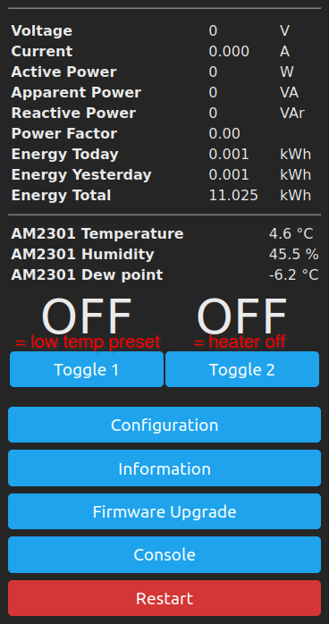
Now that energy prices vary a lot and need to be considered, easy automatized control of heater devices has gotten more important and useful than ever.
This project aims to make heaters easily remote controllable by making the "power on/off" signal (from MQTT, REST, Tasmota web UI) control the target temperature level instead of directly the resistor.
Any ESP8266 / ESP32 relay that can be flashed with Tasmota (or other suitable firmware, here I'm using Tasmota) and has at least one usable GPIO is fine, personally I prefer ones that have power measurement, like the Sonoff Pow family or Shelly PM devices.
Details to be added.
2
Setup Tasmota
By default Tasmota's "power" command directly controls the relay, but generally I'm more interested in controlling something like temperature than a relay so need to do something. I'd like to be able to set a target temperature and to easily change between at least two different preset temperatures.
The "power" command is linked to a relay, which is also linked to a button in the UI so would be convenient to use a "relay" for controlling the temperature instead of a heater resistor. Luckily Tasmota doesn't really care if a relay assigned to a GPIO really exists so one can use an unused GPIO as a "virtual relay" that will follow the "power" command and have a button in the UI:
The real relay was originally set as "1", but to allow using the plain "power on" / "power off" commands to change between low and high temperatures I configured the original relay in GPIO12 as "2" and the new virtual relay as "1".
To rename the buttons:
webbutton1 Heat
webbutton2 Resistor
webbutton3 Hold
That's all about the basic configuration, Rules to continue from there.
3
Tasmota rules
The rule to rule them all:
For every device:
Rule1
ON system#boot DO Var1 %mem1% ENDON
ON Tele-am2301#temperature<%var1% DO power2 on ENDON
ON Tele-am2301#temperature>%var1%+1 DO power2 off ENDON
ON power1#state=0 DO backlog Var1 %mem1%;RuleTimer 0 ENDON
ON power1#state=1 DO backlog Var1 %mem2%;Ruletimer %mem3% ENDON
ON Rules#Timer=1 DO power1 off ENDON
Customized for each room, here for non-living space:
backlog var1 2; mem1 2; mem2 18; mem3 10800; rule1 on
# var1 = initial thermostat value, degrees Celsius
# mem1 = lower thermostat value, degrees Celsius
# mem2 = higher thermostat value, degrees Celsius
# mem3 = high thermostat timeout, seconds
# 10800 = 3 hours as seconds, ESP32 builds also allow 3*60*60
Description:
Rule1
# Start the ruleset 1
ON system#boot DO Var1 %mem1%
# At boot copy the lower value from flash to RAM
ON Tele-am2301#temperature<%var1% DO power2 on ENDON
# When sensor (here am2301 that supports AM2302=DHT22) reports
# temperature lower than the target, turn the real relay on
ON Tele-am2301#temperature>%var1%+1 DO power2 off ENDON
# When temperature more than target + 1, turn the real relay off
ON power1#state=0 DO backlog Var1 %mem1%;RuleTimer 0 ENDON
# When state of the virtual relay 1 changed to "off", use the low value as target
# and stop timer
ON power1#state=1 DO backlog Var1 %mem2%;Ruletimer %mem3% ENDON
# When virtual relay turned on, use the high value as target
# and start the timer with value from mem3
ON Rules#Timer=1 DO power1 off ENDON
# When timer run out, turn the virtual relay off
The virtual relay, controllable by the commands "power off" and "power on" sets the target temperature from the flash-based variables mem1 and mem2.
For controlling there are three commands:
power off - Set the thermostat to the low temperature
power on - Set the thermostat to the high temperature
var1 nn - Set the thermostat to nn degrees Celsius
After setting the value with var1, changing state with power on|off will set it back to a preset temperature.
Note that "power on" will time out after the desired period and change back to the off/low state, but setting a certain temperature with var1 doesn't time out with the current set of rules.