For now, updates are only being made to the github repository.
https://github.com/edson-acordi/4bit-microcomputer
Main Features:
- Implements a 4 bit CPU
- 2k x 16 Program Memory (up to 4k)
- 2k x 4 RAM (up to 4k)
- 4 Output Ports (16 outputs)
- 4 Input Ports (16 inputs)
- Single Cycle Instruction/RISC
- Harvard Architecture
- 3 execution modes:
- step by step
- 3MHz (precise time base)
- adjustable clock speed ( ≈ 1 Hz - 200 Hz)
- No MPU/MCU or complex chips
- No microcode
- Indirect addressing to facilitate the implementation of subroutines
- Program memory implemented with RAM to easy programming
- It accepts 300 and 600 mils memories (for those with old DIP versions)
- Supercapacitor or battery to keep the program in RAM (for low power version)
- It can be manually programmed by switches or via Arduino/Esp32
- Built with 74HCTxxx integrated circuits for low power consumption and compatibility with TTL circuits
- All parts are through-hole for easy assembly
- All control signals, registers and the program counter are available through the pin header connectors
- Dual layer Single board with 295.9mm x 196.9mm
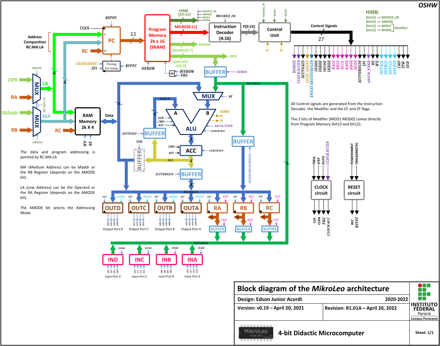
MikroLeo Architecture
Note that some buffers are used to allow viewing the contents of registers at any time, since this project is mainly intended for educational purposes.
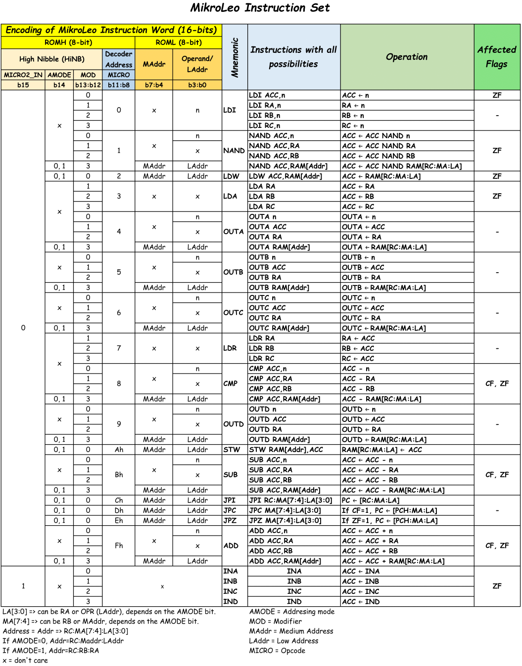
The MikroLeo Instruction Set
Although MikroLeo has only 20 instructions, using the AMODE bit (b14) and the modifier bits (b13:b12), it is possible to encode 64 combinations of instructions, as can be seen below.
Instruction Set explanation and examples
In binary, the Instruction Word is coded as,
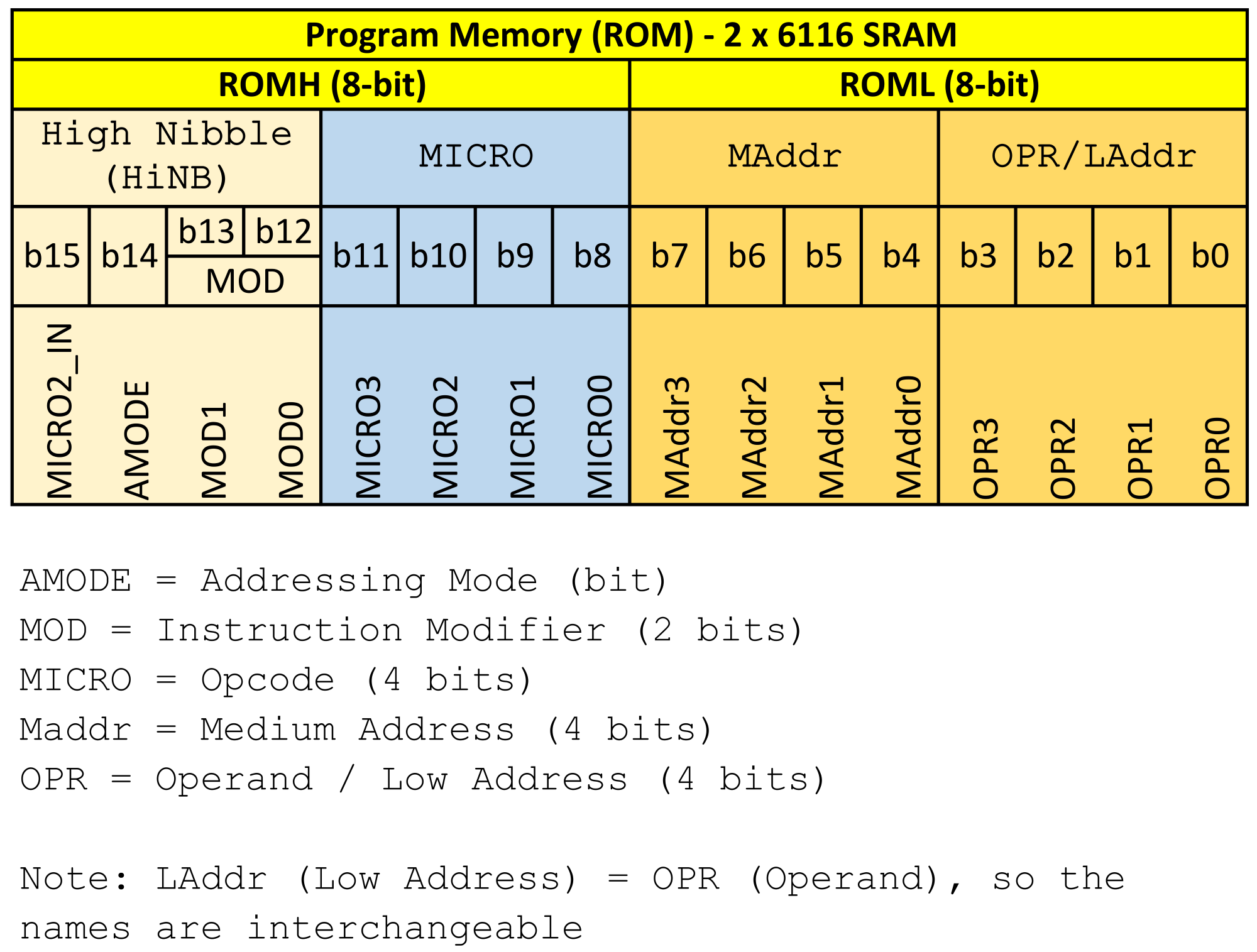
ROMH (Most significant byte of program memory)
| b15 | b14 | b13 | b12 | b11 | b10 | b9 | b8 |
|---|---|---|---|---|---|---|---|
| MICRO2_IN | AMODE | MOD1 | MOD0 | MICRO3 | MICRO2 | MICRO1 | MICRO0 |
ROML (Least significant byte of program memory)
| b7 | b6 | b5 | b4 | b3 | b2 | b1 | b0 |
|---|---|---|---|---|---|---|---|
| MAddr3 | MAddr2 | MAddr1 | MAddr0 | Operand3 | Operand2 | Operand1 | Operand0 |
- Note: b15 = bit15 ... b0 = bit0
LDI - Load with Immediate
Description: Loads the operand value into a register.
Registers: ACC, RA, RB or RC
Operation: Register <─ Operand
| Instruction Word | ROMH | Instruction | Affected Flags |
| 0x00xn | 0x00 | LDI ACC,n | ZF |
| 0x10xn | 0x10 | LDI RA,n | - |
| 0x20xn | 0x20 | LDI RB,n | - |
| 0x30xn | 0x30 | LDI RC,n | - |
Examples,
| Instruction Word | Instruction | Comment |
| 0x0005 | LDI ACC,5 | Load ACC with operand |
| 0x1006 | LDI RA,6 | Load RA with operand |
| 0x2007 | LDI RB,7 | Load RB with operand |
| 0x300a | LDI RC,10 | Load ACC with operand |
The Instruction Word, for example, for LDI RA,6 is coded as,
0x1006
  ┆┆┆└──> Least significant Nibble => Operand[b3:b0] = 6
  ┆┆└───> Second Nibble => MAddr[b7:b4] = 0
  ┆└────> Third Nibble => MICRO[b11:b8] = 0
  └─────> Most significant Nibble => HiNB[b15:b12] = 1
Also, the instruction word (in binary) to be manually programmed into MikroLeo using physical switches is,
0001 0000 0000 0110
  ┆    ┆    ┆    └─> Operand = 6
  ┆    ┆    └──────> MAddr = 0 (For this instruction, it doesn't matter)
  ┆    └───────────> MICRO = 0 (OPCode)
  └────────────────> HiNB = 1 (MICRO2_IN = 0, AMODE = 0, MOD = 1)
NAND - bitwise Nand
Description: Performs the bitwise Nand operation between ACC with (Operand n, RA, RB or RAM).
The result is stored in ACC.
Operations:
ACC <─ ACC NAND Operand
ACC <─ ACC NAND Register
ACC <─ ACC NAND RAM
| Instruction Word | ROMH | Instruction | Affected Flags |
|---|---|---|---|
| 0x01xn | 0x01 | NAND ACC,n | ZF |
| 0x11x0 | 0x11 | NAND ACC,RA | ZF |
| 0x21xn | 0x21 | NAND ACC,RB | ZF |
| 0x31mn | 0x31 | NAND ACC,@RAM | ZF |
| 0x71xx | 0x71 | NAND ACC,@R | ZF |
Note:
The RAM address for @RAM is pointed by RC:MAddr:LAddr.
The RAM address for @R is pointed by RC:RB:RA.
The MAddr is represented by the letter "m".
Examples:
| Instruction Word | Instruction | Comment |
|---|---|---|
| 0x0105 | NAND ACC,5 | NAND operation between the accumulator and the operand and stores it in ACC |
| 0x1106 | NAND ACC,RA | NAND operation between the accumulator and register RA and stores it in ACC |
| 0x2107 | NAND ACC,RB | NAND operation between the accumulator and register RB and stores it in ACC |
| 0x310a | NAND ACC,@0x0a | NAND the contents of the RAM address with ACC and stores it in ACC. In this case, the RAM address = RC:0:a |
| 0x7100 | NAND ACC,@R | NAND the contents of the RAM address with ACC and stores it in ACC. In this case, the RAM address = RC:RB:RA |
The Instruction Word, for example, for NAND ACC,5 is coded as,
0x0105
  ┆┆┆└──> Least significant Nibble => Operand[b3:b0] = 5
  ┆┆└───> Second Nibble => MAddr[b7:b4] = 0
  ┆└────> Third Nibble => MICRO[b11:b8] = 1
  └─────> Most significant Nibble => HiNB[b15:b12] = 0
Also, the instruction word (in binary) to be manually programmed into MikroLeo using physical switches is,
0000 0001 0000 0101
  ┆    ┆    ┆    └──> Operand = 5
  ┆    ┆    └───────> MAddr = 0 (For this instruction, it doesn't matter)
  ┆    └────────────> MICRO = 1 (OPCode)
  └─────────────────> HiNB = 0 (MICRO2_IN = 0, AMODE = 0, MOD = 0)
...
Basic Documentation
- MikroLeo has four RegistersACC - Accumulator (4 bit) - Stores the result of logical and arithmetic operations. Moreover, ACC stores data that is read from or written to RAM.RA - 4 bit General purpose Register (also used for addressing).RB - 4 bit General purpose Register (also used for addressing).RC - 4 bit Special purpose Register used for addressing.
- Two Flags
Flags can only be checked by conditional jump instructions (JPC and JPZ).
CF - Carry Flag - It is Set (CF=1) by ADD Instruction if it produces a carry or by SUB/CMP instruction if it results in a borrow.ZF - Zero Flag - It is affected by operations that modify the contents of the ACC and by CMP instruction. It is Set (ZF=1) if the result of the last operation was zero.
Example of how CF and ZF are Set:
LDI ACC,1
ADD ACC,0xF
This code does it,
   0001
+  1111
-------
 1 0000
 ↓   ↓
CF  ACC

As the value zero is written to ACC, ZF=1.
- Addressing Modes
Immediate
In immediate addressing, the operand (n) is contained in the lower nibble of the instruction (b3:b0), and it is denoted by Operand, LAddr or OPR.
Example 1:
LDI ACC,1 ;Load the operand value into the ACC accumulator.
Example 2:
LDI ACC,0xA
Example 3:
NAND ACC,0   ;Performs the NAND operation between the accumulator and the
             ;operand value and stores the result in the accumulator.
Example 4:
OUTA 0xF ;Sends the operand value to the OUTA output port.
Example 5:
CMP ACC,0    ;Performs the comparison between the accumulator and the
             ;operand.
Example 6:
SUB ACC,1    ;Performs the subtraction between the accumulator and the
             ;operand and stores the result in the accumulator.
Example 7:
ADD ACC,5    ;Performs the addition between the accumulator and the
             ;operand and stores the result in the accumulator.
Register Direct
In this mode, the operand must be one of the four registers (ACC, RC, RB, RA). Thus, the contents of the lower and medium nibble of the instruction (MAdrr, b7:b4 and LAddr, b3:b0) do not matter. Note that in the LDR instruction, the operand (ACC) is implied. LDR stands for load the Register Rx with ACC, being x={A,B,C}. In the LDA instruction, the operand must be one of the three registers (RC, RB, RA). LDA stands for load the accumulator with one of Rx Registers. Note that in register direct addressing mode, data can be read from or written to a register.
Example 1:
LDR RA ;Loads the value of the ACC accumulator into the RA register.
Example 2:
LDR RB ;Loads the value of the ACC accumulator into the RB register.
Example 3:
LDA RA ;Loads the value from the RA Register into the ACC accumulator.
Example 4:
LDA RC ;Loads the value from the RC Register into the accumulator ACC.
Register Indirect + Absolute
In this addressing mode, the RC Register points to the high address (b11:b8). The medium (MAddr) and low (LAddr) nibble of the instruction, point to the medium and low address, respectively.
The final address is composed by RC:MAddr:LAddr.
For example, if:
RC = 3 MAddr = 2 LAddr = 1
The address to be accessed is 321h.
In the MikroLeo python assembler, absolute addresses (MAddr:LAddr) are indicated by an @.
Example 1:
  LDI RC,1       ;Loads the operand value into the RC Register.
  OUTA @0xF4     ;Sends the contents of the RAM address pointed to by
                 ;RC:MAddr:LAddr to output port A, in this case, the RAM
                 ;address is RC:MAddr:LAddr = 1F4h.
Example 2:
  LDI RC,3       ;Loads the operand value into the RC Register.
  ADD ACC,@0xFC  ;Sum the contents of the RAM address pointed to by
                 ;RC:MAddr:LAddr with ACC and stores it in ACC. In this
                 ;case, the RAM address is RC:MAddr:LAddr = 3FCh.
Example 3:
  LDI RC,1       ;Loads the operand value into the RC Register.
  JPI @0x23      ;Jumps to the specified label. In this case, the label
                 ;address is RC:MAddr:LAddr = 123h.
Example 4:
  LDI RC,2       ;Loads the operand value into the RC Register.
  CMP ACC,0      ;Compares the contents of ACC with the operand. Is ACC
                 ;equal to 0?
  JPZ @0x34      ;Jumps to the specified label if ZF=1 (ACC = 0). In this
                 ;case, the label address is RC:MAddr:LAddr = 234h.
Example 5:
LOOP:    LDI RC,3       ;Loads the operand value into the RC Register.
         STW ACC,@0x21  ;Stores the contents of the accumulator in the RAM
                        ;address pointed by RC:MAddr:LAddr, in this case,
                        ;the RAM address is RC:MAddr:LAddr = 321h.
         LDI RC,>LOOP   ;Gets the address of the label, as this code changes
                        ;the contents of the Register RC.
         JPI LOOP       ;Jumps to the specified label.
Example 6:
LOOP:    LDI RC,3       ;Loads the operand value into the RC Register.
         LDW ACC,@0x21  ;Loads the contents of the RAM address pointed by
                        ;RC:MAddr:LAddr in the accumulator, in this case,
                        ;the RAM address is RC:MAddr:LAddr = 321h.
         LDI RC,>LOOP   ;Gets the address of the label, as this code changes
                        ;the contents of the Register RC.
         JPI LOOP
Example 7:
LOOP:    LDI RC,4       ;Loads the operand value into the RC Register.
         CMP ACC,@0x32  ;Compares the contents of ACC with the contents
                        ;of the RAM address pointed by RC in
                        ;this case, the RAM address is RC:MAddr:LAddr = 432h.
                        ;Is ACC equal to @432h?
         LDI RC,>LOOP   ;Gets the address of the label, as this code changes
                        ;the contents of the Register RC.
         JPZ LOOP       ;Jumps to the specified label if ZF=1 (ACC = @432h).
Register Indirect
In this addressing mode, the RC Register points to the high address (b11:b8). Likewise, the RB Register points to the medium Address (MA) while the RA Register points to the low Address (LA). Note that the contents of the lower and medium nibble of the instruction (MAddr, b7:b4 and LAddr, b3:b0) do not matter.
The final address is composed by RC:RB:RA.
For example, if:
RC = 3 RB = 2 RA = 1
The address to be accessed is 321h.
In MikroLeo's python assembler, indirect register addresses (RC:RB:RA) are indicated by an @R.
Example 1:
  LDI RC,1       ;Loads the operand value into the RC Register.
  LDI RB,0xF
  LDI RA,4
  OUTA @R        ;Sends the contents of the RAM address pointed to by
                 ;RC:RB:RA to output port A, in this case, the RAM address
                 ;is RC:RB:RA = 1F4h.
Example 2:
  LDI RC,3       ;Loads the operand value into the RC Register.
  LDI RB,0xF
  LDI RA,0xC
  ADD ACC,@R     ;Sum the contents of the RAM address pointed to by RC:RB:RA
                 ;with ACC and stores it in ACC. In this case, the RAM
                 ;address is RC:RB:RA = 3FCh.
Example 3:
  LDI RC,1       ;Loads the operand value into the RC Register.
  LDI RB,2
  LDI RA,3
  JPI @R         ;Jumps to the specified label. In this case, the label
                 ;address is RC:RB:RA = 123h.
Example 4:
  LDI RC,2       ;Loads the operand value into the RC Register.
  LDI RB,3
  LDI RA,4
  CMP ACC,0      ;Compares the contents of ACC with the operand. Is ACC
                 ;equal to 0?
  JPZ @R         ;Jumps to the specified label if ZF=1 (ACC = 0). In this
                 ;case, the label address is RC:RB:RA = 234h.
Example 5:
LOOP:    LDI RC,3       ;Loads the operand value into the RC Register.
         LDI RB,2
         LDI RA,1
         STW ACC,@R     ;Stores the contents of the accumulator in the RAM
                        ;address pointed by RC:RB:RA, in this case, the RAM
                        ;address is RC:RB:RA = 321h.
         LDI RC,>LOOP   ;Gets the address of the label, as this code changes
                        ;the contents of the Register RC.
         JPI LOOP       ;Jumps to the specified label.
Example 6:
LOOP:    LDI RC,3       ;Loads the operand value into the RC Register.
         LDI RB,2
         LDI RA,1
         LDW ACC,@R     ;Loads the contents of the RAM address pointed by
                        ;RC:RB:RA in the accumulator, in this case, the RAM
                        ;address is RC:RB:RA = 321h.
         LDI RC,>LOOP   ;Gets the address of the label, as this code changes
                        ;the contents of the Register RC.
         JPI LOOP
Example 7:
LOOP:    LDI RC,4       ;Loads the operand value into the RC Register.
         LDI RB,3
         LDI RA,2
         CMP ACC,@R     ;Compares the contents of ACC with the contents of
                        ;the RAM address pointed by RC in
                        ;this case, the RAM address is RC:RB:RA = 432h.
                        ;Is ACC equal to @432h?
         LDI RC,>LOOP   ;Gets the address of the label, as this code changes
                        ;the contents of the Register RC.
         JPZ LOOP       ;Jumps to the specified label if ZF=1 (ACC = @432h).
Assembler Compiler
Almost ready...
How to transfer compiled program to MikroLeo
Almost ready...
Emulator
In progress...🚧
Some Pictures
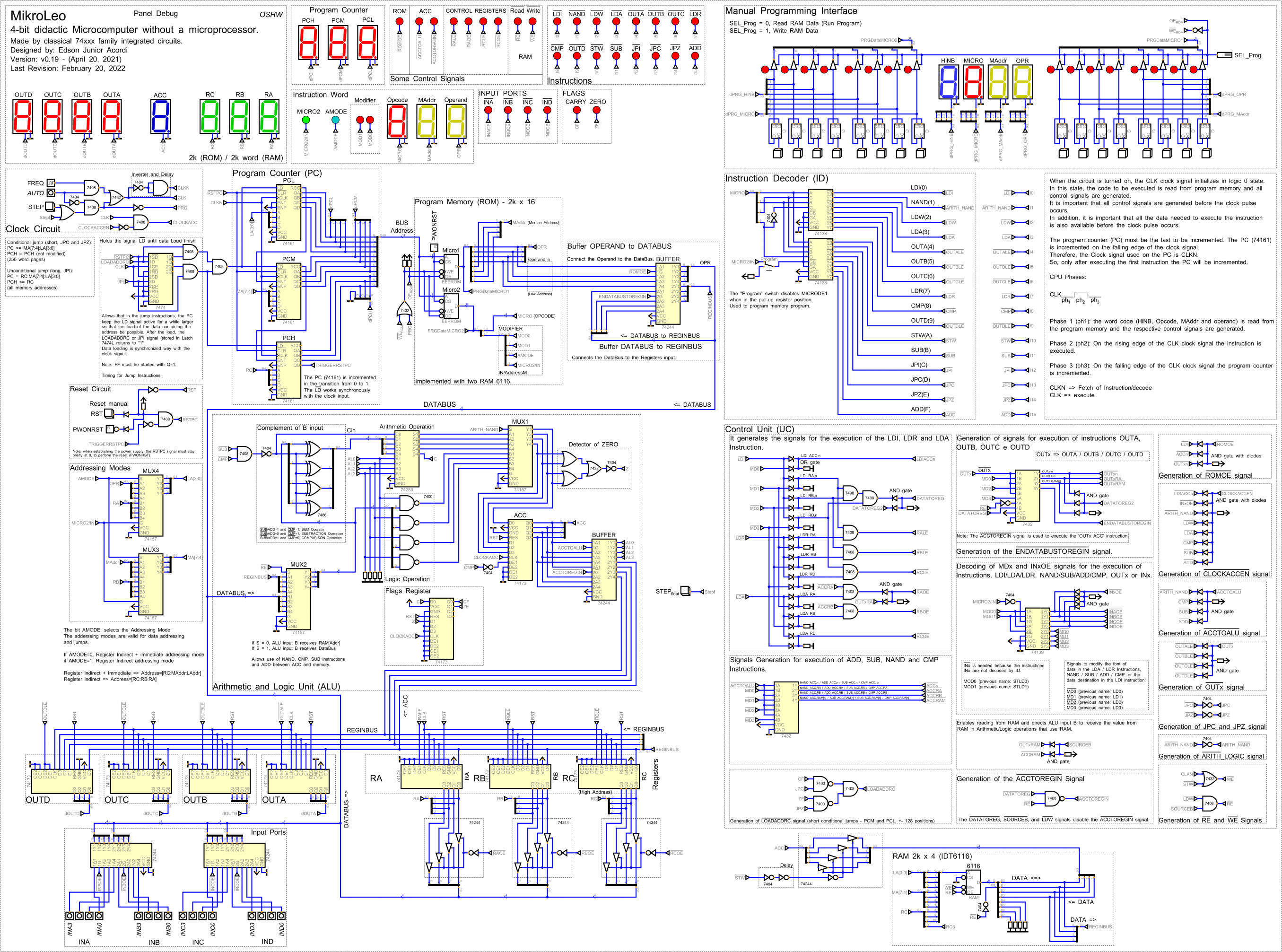
Simulation of the MikroLeo circuit (Made with "Digital"):
Digital is free, open source and cross-platform software with a nice interface for digital logic design and circuit simulation.
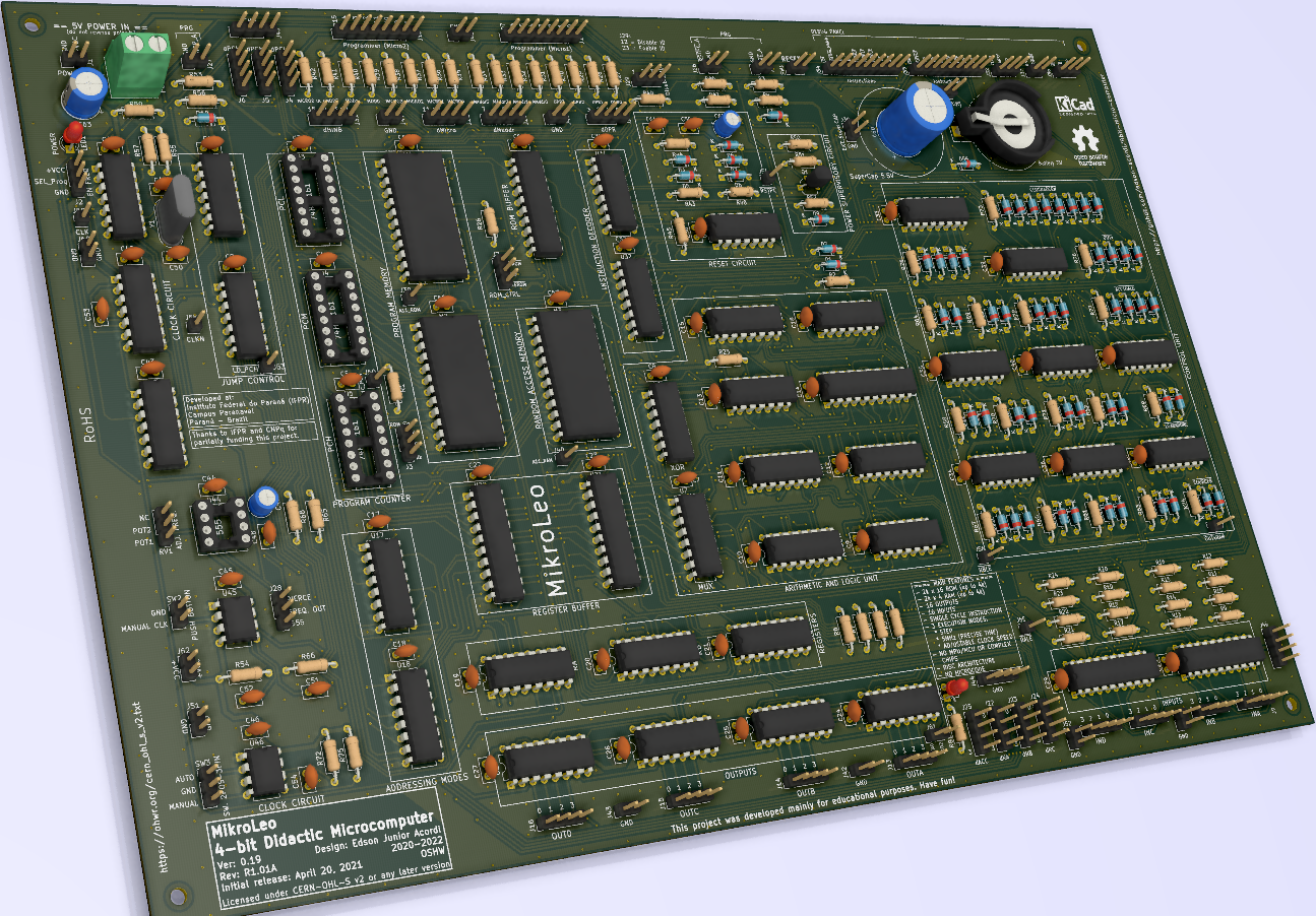
PCB (KiCad 3D viewer):
To carry out the project, the KiCad software was used, an excellent and powerful free and open-source tool for printed circuit board (PCB) designers.
Development stages
- Bibliographic research - [completed]
- Architecture definition - [completed]
- Circuit design - [completed]
- Circuit simulation - [completed]
- Prototype assembly on breadboard - [completed]
- Printed circuit board design - [completed]
- Prototype assembly on PCB - [completed]
- Final Tests - [almost finished]
History and Motivation
Since the time I took an 8086 assembly language programming course and took digital electronics and microprocessors classes in college, this project has been something I've always wanted to do. I'm fascinated by electronics, computers and programming!
The project started in 2020, and the first usable version was completed on April 20, 2020.
Initially, the development of the project used the Logisim-Evolution, and later it was migrated to the Digital.
Dedication
I dedicate this project to my beloved son, Leonardo Pimentel Acordi.
Acknowledgements
The authors would like to thank:
- The IFPR (Instituto Federal do Paraná), CNPq (Conselho Nacional de Desenvolvimento Científico e Tecnológico) and Fundação Araucária for the partial funding and support for this project.
- The RENESAS (https://www.renesas.com/br/en) for sending me memory samples for tests with MikroLeo.
- All people from the hackaday.io community, Github community and external people who support this project.
Authors
Edson Junior Acordi
Matheus Fernando Tasso
Carlos Daniel de Souza Nunes
License
Hardware: Licensed under CERN-OHL-S v2 or any later version
https://ohwr.org/cern_ohl_s_v2.txt
Software: Licensed under GNU GPL v3
https://www.gnu.org/licenses/gpl-3.0.txt
Documentation: Licensed under CC BY-SA 4.0
https://creativecommons.org/licenses/by-sa/4.0/
Note:
As this project is intended for educational purposes, I have decided to use the CERN-OHL-S license for hardware to ensure that it is always free, contributing, promoting and disseminating the essential knowledge. As such, all hardware derived from it will also be open source!
Likewise, for the software, the GNU GPL license was used.
For now, updates are only being made to the github repository.
https://github.com/edson-acordi/4bit-microcomputer
As soon as possible, I will put everything here!