sparks.ron
-
Figuring out the GPIO needs
02/07/2017 at 17:43 • 0 commentsWhat I need now is an inventory of all the interfaces that my potential sensors would require. I took the list from the previous log and put it in a spreadsheet. Then I went through each datasheet and looked at the interfaces.
Here are the results if I were to put in every sensor:
3 – Dallas one-wire type 6 – I2C 1 – SPI 3 – digital I/o (pulse, data/clk, etc) 1 – serial I/0 6 – analog (volts or current) 1 – AC resistance From this I can now do a quick look to see what interfaces I need to augment for the Arduino style inputs. The Arduino A/D system does not have the accuracy or range this project needs so an outboard chip will be required. From the above I can see an 8 input multiplexed IC with an I2C interface would be a good choice. For example I will look further into the $2 TI ADC128D818.
-
Quick Thoughts
01/05/2017 at 19:41 • 0 commentsI did not elaborate on my direction with some of the more unusual sensors. Here are a few quick thoughts:
- The various photodetectors will be used to measure the illumination with a rough spectral breakout. In other words IR, R, G, B, and UV.
- Additionally a more traditional illumination measurement will be done that can correlate to the output of a fixed, tilted solar panel. In this regard I am thinking about using an IR thermopile to measure solar irradiance (W/m²)
- The Watermark sensors will be placed at a depth of about 1m (3ft) and 20cm (8 inches) to give a relative measurement of soil moisture in the tree root zone and grass root zone, respectively. The waterproof temperature sensors will be buried along with them for soil temperature measurements.
- Separate to this project I will follow with an evaporation pan system to allow estimations of leaf water loss. The current project should have an interface to allow other sensors like the evaporation system to "just plug in".
- The GPS module would be used to provide very accurate real times for data timestamping. It could also monitor any location deviations for inexpensive precision differential GPS. This would be a big help for things like bee hive siting, tree planting, fences, etc.
- Relative humidity and dewpoint are notoriously difficult to measure accurately. The reason for having two high accuracy temperature sensors is to allow the construction of a dry bulb-wet bulb arrangement. This will allow traditional methods to be used as well as the digital humidity sensors. I am curious to see what the comparative levels of accuracy are.
- The microphone output will be monitored for large peaks (like thunder) which could enhance the data from the lightning detector. It will also be used for very long term (hourly?) averaging to create a baseline background noise measurement. Subjectively I have noticed a large increase in noise as the city of Houston grows nearer us.
- I am still researching to determine if there is a very low cost leaf wetness sensor that can be incorporated into this system. Usual sensors are simple resistive or capacitive probes (printed circuit boards), but it seems to me that they would need continuous maintenance to remove dirt and dust.
-
What sensors do I have?
01/04/2017 at 20:01 • 0 commentsI dug through my "junk box" to see what sensors I have acquired over the last couple of years. I anticipated building enhancements to the existing consumer weather stations, but found that closed software and proprietary protocols were not friendly to the process. As I mentioned that , plus the failure of my third consumer station (2 Davis & 1 Peet Bros.), motivated me to just build the complete thing.
Here is a list of what I found in my project box (-10 to 50 °C typical accuracies listed):
- 6ea - DS1620 digital temperature sensor, ± 2.0 °C
- 6ea - DS18B20 digital temperature sensor, ± 0.5 °C (2ea waterproof probes)
- 1 ea - HTU210F digital temperature + humidity sensor, ± 0.3 °C, ± 2%RH
- 4ea - SHT11 digital temperature + humidity sensor, ± 0.4 °C, ± 3%RH
- 2ea - MCP9808 digital temperature sensor, ± 0.25 °C
- 1ea - HM55B digital compass sensor, ± 9 μT
- 1ea - MPL3115A2 digital pressure sensor w/altimetry, ± 0.4 kPa
- 1ea - LSM303DLHC digital accelerometer + magnetometer, ± 60 mg, ± 1.3 μT
- 1ea - PR300A? (Fairchild 5154-20) selenium photocell, >10Meg dark, approx 500 ohm light
- 1ea - AS3935 Franklin Lightning Sensor, TBD, greater than noise floor (can set from 28-2000 μVrms)
- 3ea - RT100 platinum temperature sensor, ± 0.5 °C
- 1ea - CMA-4544PF-W microphone + MAX4466, combined calculated at ±3.5 dBV
- 4ea - various light sensors (more on these later)
- 2ea - Anemometers + wind direction, need rebuilding due to wear
- 2ea - Tipping bucket rain gauge sensors, 8 inch, 0.01 inch accuracy
- 3ea - Watermark soil moisture sensors, accuracy depends on soil - must be calibrated
- 2ea - Unknown type GPS modules, likely USGlobalsat with SiRF StarIII chipset
As I mentioned all of these were acquired over the last two years and ranged from a few cents at hamfests/swapmeets to about $7-12 USD for those on breakout boards. Nearly all of the above (or their improved successors) are available from Adafruit.com currently. I highly recommend them as a source for any DIY sensors and/or breakout boards for prototyping.
One of the stated objectives of this project is to have high inherent accuracy to eliminate, or at least simplify, the calibration of the final station.
In the discussion a suggestion was made to make this unit wireless. That is a nice goal for "Phase 2", along with solar power. However, to keep things simple and prove the concept I will make the prototype and initial station as wired with PoE. That will allow it to run on a single Cat5e direct burial cable and will allow for actual power consumption evaluation in preparation for solar power.
My research on the Stevenson Screen also turned up several papers and in-depth measurement comparisons for natural measurements versus aspirated (fan driven) measurements. Surprisingly the aspirated "gold standard" was invented and has been in use since the late 1800's. A LOT of data is, therefore, available.
From all this, I am leaning toward having both types of sensors in the initial proof of concept system. My conclusion from the papers is the natural aspiration tends to be good at providing stable, consistent measurements where the aspirated ones are superior in measuring rapid changes and layering.
-
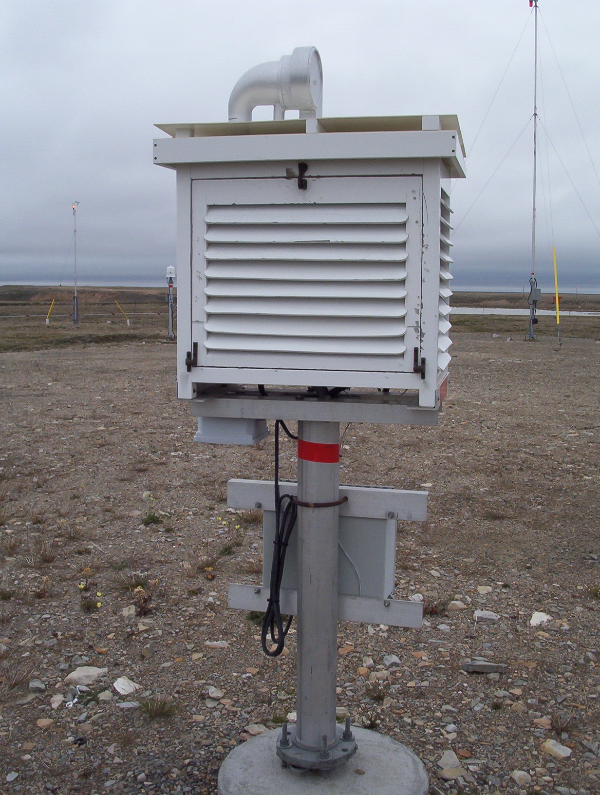
The Stevenson Screen
12/12/2016 at 23:09 • 0 comments![]()
photo Kindly placed in the public domain by Cambridge Bay Weather
The familiar box that houses various weather instruments has an interesting origin. The father of the famous author Robert Louis Stevenson (Dr. Jekyll and Mr. Hyde, Treasure Island, etc.) was a British civil engineer who specialized in lighthouse design. He realized that the lack of standardization of how weather data was measured and recorded was causing inaccurate results and incorrect analyses.
He created a standard for the small double-louvered box with no floor in the middle 1860s. It was later modified to include the double roof and was ultimately adopted as the standard for the British Meteorological Society in 1884. Apparently there have been a number of regional variants including one for the "Cotton Region" of the US. I was surprised today to find that one of the regularly cited works for that is "The Effect of Thermometer Screen Design on the Observed Temperature", W.R. Sparks. It would be fun to find out if W. R. is a distant relative of mine.
According to Wikipedia the traditional interior size for a single unit (like the photo) "may be" 76.5 by 105 by 59.3 centimetres (30.1 by 41.3 by 23.3 in). In my reading of other papers it appears that there is a huge variation on those dimensions. Obviously given my current location in the Texas Gulf Coast (which may include "cotton" region), I will attempt to track down the 1972 paper on screen design and other design comparisons.
Because my budget does not allow me to buy a pre-made screen. I will be designing and building my own. I have learned a lot of "life lessons" regarding the design of outdoor equipment for use here in Texas and in most of the more than 3 dozen countries I have had the opportunity to work in. More on that to come.
-
What is my current status?
12/12/2016 at 17:59 • 0 commentsAs I noted this project log is starting reasonably far into the actual project itself. If you want to see my approach and how I got to here, I will answer things in the discussion section but there is little sense in blogging it. On my Gamma Scintillation project I will be blogging a lot of the methods that got me to today on this project, so there is no need to repeat them here.
This project got pushed into the "holding box" (a literal box) when my life situation changed this summer. The restart on this now will begin with an inventory of what is in that box and what has been prototype vs what needs to be done.
In general I had the Arduino base unit working and talking successfully to a temperature/humidity sensor and tested that over a long-ish distance piece of Cat5e between the Arduino and the sensor. My reasoning was to ensure I could read data for both "inside" and "outside" the unit. Those terms are a bit arbitrary because the three application scenarios I have here are:
- Generic accuracy indoor/outdoor measurement for energy consumption analyses.
- High accuracy outdoor weather/climate station. In that case "inside" would be in the case holding the electronics and the "outside" would be the actual measurement being performed inside of a Stephenson Screen a couple of feet away. My plan is to house the electronics and such separately from the real measurement sensors to minimize any localized self-heating, etc.
- Flight ready balloon launch package. In this case "inside" is the interior of the payload and "outside" is the atmosphere around the payload/balloon. It is important on balloon flights that we minimize the change to the electronics inside the payload. We use repurposed Styrofoam chests to help moderate the temperature changes from launch, through flight, to recovery. Here in the Texas Gulf Coast it is not unusual for launch to occur at 90F (32C), pass through the stratosphere at -65C (-85F), increase at upper altitudes to -20C (-4F), and then reverse back through to 90F at landing. COTS hardware could not stand that if it weren't for some reduction in the swing along with the short-ish (± 5 hrs) time of exposure.
I also remember having the barometric sensor working as well as the high accuracy temperature sensor. Where things stopped was just as I was beginning to put multiple sensors on the data bus simultaneously.
I had done a bit of experimenting with the pulse output of anemometers and wind direction indicators. With that I began gathering scientific research on how to calculate an anemometer's relationship with true wind speed. My hardware prototyping was hindered by cable and connector issues with my existing anemometer setup, along with some very calm days that gave me zero output.
At this point I will restart by getting out the project box and doing some photography of what bits I have.
Climate & Environment Monitoring Station
Create a monitoring station to measure weather, soil, seismic, solar, magnetic, and gravity conditions - focus best accuracy/dollar w/COTS.