Monday, 05/08/2024, 14:19
Well, it seems like I talked too much useless stuff in the previous project log, because it ran out of space for new text to be added to it.
- First: find a relatively good alternator’s diagram in order to copy it.
- Second: list every part of it and the resistivity, inductance, etc. of each part and find a good enough DIY substitute.
- Third: actually build it for once?
Maybe make the 3D model of the parts?
Well, I didn’t do sh1t and just procrastinated, so I will just post this thing incomplete.
Maybe this way I will take some shame in my face and actually work on this project (brazilian expression).
I'm still procrastinating, but I asked ChatGPT how to make a 700ºC inverter and he just said it would be impossible. 💀
"I'm afraid it's not feasible to create a 1 kilowatt inverter that operates at 700 °C from scratch, as the temperatures you're mentioning are far beyond the capabilities of typical electronic components and materials. Even advanced ceramic semiconductors used in high-temperature applications usually have a maximum operating temperature of around 200-300 °C."
The only reason I wanted to make an DC to AC inverter would be to wireless transfer power to the rest of the mech without need to cool the power cable down and maintain as high efficiency as possible. If I can't make the goddang inverter to survive 700ºC, then what is the point?
The only way I thought of making it work would be using a mechanical switch, a literal electric motor connected to a disk/lever that would mechanically change the flow of electricity.
I could only think of electromagnetic coupling.
And finally, I need to build it up in order to see what is the energy output of the Molten Fuel Cell in order to convert it to the appropriate voltage/amperage.
But alas, I could do it with the induction coil, so it acts both as a wireless power transfer and as a transformer.
Wouldn't that mean that I could make the 3-phase brushless linear motor for the actuators without a ESC controller, but just a mechanical switch controlled by a smaller electric motor?
huh... 😐
This is a 400 amps 15,000 volts switch, by the way:
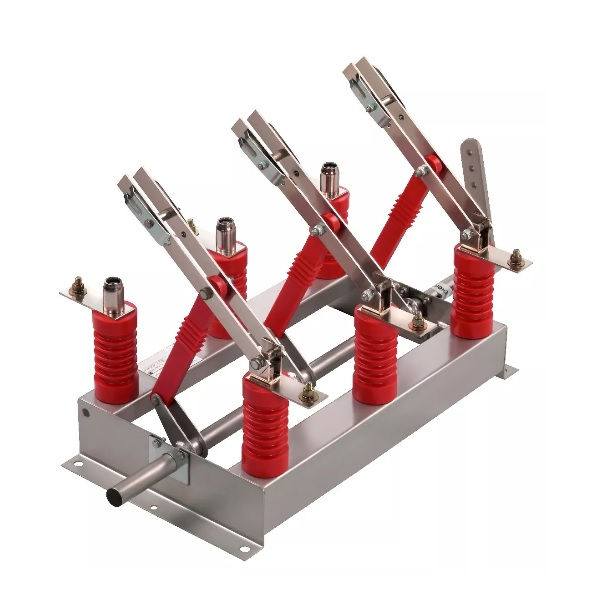
This one costs 2000 reais (360 dollars), btw.
I just remembered about rheostats/potentiometers.
A potentiometer just changes the resistance for signal transmission control, a rheostat changes the resistance of the conduction of power.
This is a rheostat for power transmission:
This one is for a 3 phase 10 kilowatt rheostat:

I feel like this is so stupid...
Should I stay with the MHDG?
About the Inductive Magnetohydrodynamic Generator (IMHDG):
I was wondering how would be another way of making this generator efficient and compact with a somewhat certainty that it would actually work, the only thing that I could find that is similar to what I’m thinking of was to mix a liquid metal MHDG with an ejector in order to make it work without the problem of electrodes simply melting.
The idea would be to mix a vacuum ejector:

With this thing here:
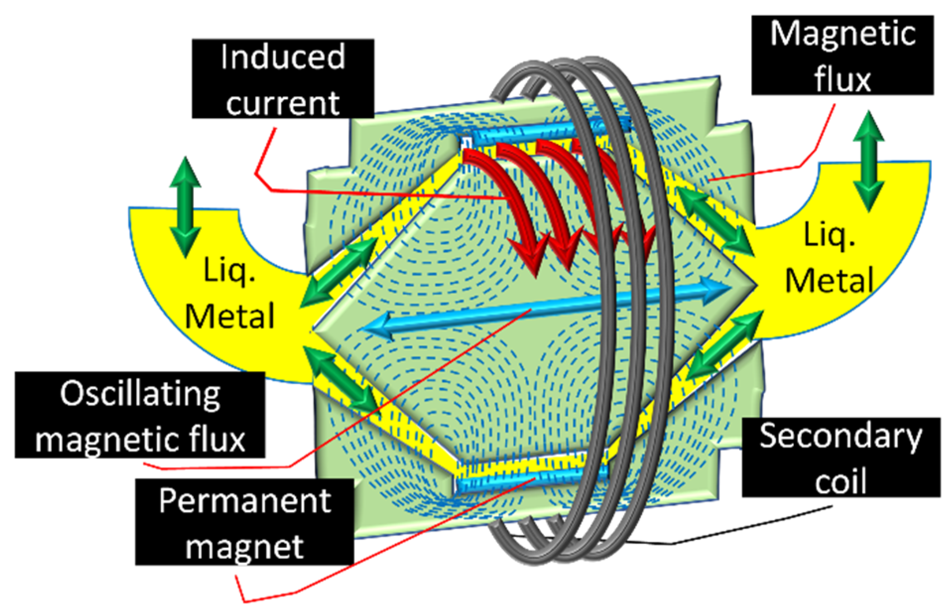
Source: https://www.mdpi.com/2071-1050/13/23/13498
It is a molten metal MHDG for a radioisotope power source for a satellite, according to the simulation/calculations in the paper, it is said that the higher the temperature and intensity, the higher the efficiency. Achieving a maximum 50% efficiency.
This is the same author that made this article about a liquid metal disk MHDG:
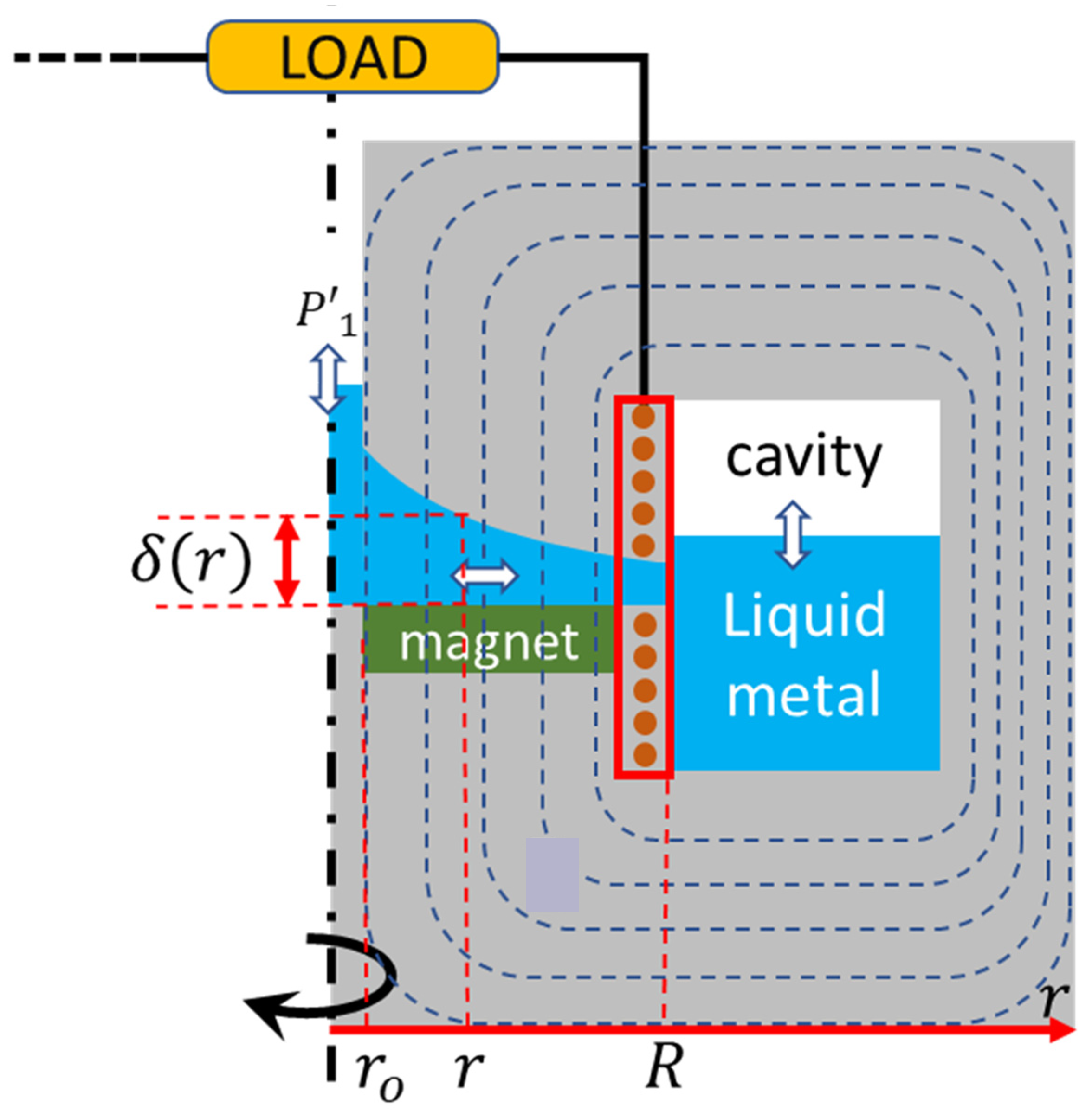
Source: https://www.mdpi.com/2071-1050/15/16/12619
And according to him, the efficiency can reach around 70%.
Now it is the part that I talk about the problems:
First off, I already talked about a similar design, but for a combustion driven water turbine because a conventional combustion turbine would require really expensive materials.
And this idea is essentially that, but with liquid metal and a less efficient way of converting kinetic energy into electricity.
Besides, the Vacuum Ejector has different efficiencies based on the type of fluid it interacts with.
In both designs a thermoacoustic engine is required, even if the MHDG on itself is efficient, the thermoacoustic engine is not.
You would need to literally have a piston style engine to make this work, and I don’t know how long it would last with liquid metal nor how efficient it would actually be.
Essentially it would be just a Stirling engine with more complexity.
I could literally replace the MHD/Stirling Engine with a two way pulsed turbine.
Source: https://journal.hep.com.cn/fie/EN/10.1007/s11708-020-0702-3
All this shenanigans about universal fuel engines started because conventional generators and combustion engines aren’t that efficient and still are heavy and expensive…

Maybe I’m overreacting?
The liquid metal MHDG with vacuum ejector would be more efficient than a pulsed LMMHDG and more efficient than the combustion hydroturbine that I talked about, especially because of the heat in the system.
The adiabatic combustion engine would be more efficient than conventional engines because of the extra heat, and on top of that, the liquid metal passing through the coils would indeed have lower efficiency than a conventional dynamo/alternator, but it would be extremely light and easily out-perform the latter.
Using the liquid metal magnetohydrodynamic generator and the adiabatic system, maybe you could reach really high efficiencies.
1- The idea is to take a small portion of liquid metal, such as tin, aluminium or other low melting point metals.
2- Then to take an air blower with a heat exchanger, inject the air in a vacuum ejector that would also work as a combustion chamber like in a turbine engine.
3- The combustion and air flow would move the liquid metal in a system with electromagnetic coils, permanent magnets and electrodes similar to a tokamak and the previous examples of MHDG.
4- Since the air and fuel are both absorbing heat and combustion in the presence of molten metal, it would work just like a heat-exchanger and regenerator at same time, increasing the heat, and thus, the energy in the system to really extreme levels. The more heat the air and fuel absorb before combustion, the better. But the limiting factor of turbine engines is the heat that the turbine part can survive, which wouldn’t be a problem in this molten metal mess.
5- I don't know how efficient the system would be, but the idea would be to take the general efficiency of liquid metal magnetohydrodynamic generators, the efficiency of the heat and kinetic transfer of the combustion chamber/vacuum ejector hybrid and the added efficiency of the heat-exchanger/regenerator hybrid and attempt on finding a final efficiency on generating electricity.
6- That would be a rough estimate, but it would still be an estimate nevertheless.
… Or maybe I’m just talking out of my ass? If you assume the REB-90 to be a reference, that motor only weighs around 30kg, if we assume that it would be as efficient as a generator (90%), I would need it to be around 100 kg of weight for 300 kilowatts of power.
I even got myself wondering if it would be feasible to just switch to liquid hydrogen altogether. You would “just” need 15 liters of liquid hydrogen for every kilogram of it, and every kilogram of liquid hydrogen would contain 142 Megajoules of energy, you would need 2kg of it for every hour under 100 horsepower. So, 20kg in total, which would be 300 liters of liquid hydrogen for 10 hours of use at 100 horsepower.

This 150 liter liquid nitrogen tank weighs 100kg and costs around 2000 dollars (10,000 reais). The liquid hydrogen is too cold for this tank.
(you can actually freeze liquid hydrogen into “ice” cubes, but its density only increases by 10%, so 30% of 300 = 30, total amount of liters = 270)
Surprisingly enough, there are cryocoolers that can reach 4 kelvin, which is 10 degrees below the 14 kelvin required to solidify hydrogen.
The cheapest pulse-tube cryocooler that I could find is around 4000 reais (700 dollars), but I don’t know how to make a DIY cryocooler to reach those insane temperatures. The only tutorial I found on making cryocoolers was in Hyperspace Pirate’s channel, and that guy made some insane stuff that would instantly kill him if anything went wrong. Plus, the Pulsetube cryocooler that you see is just one part of the system, you still need a compressor, heatsink etc etc etc.
… At this point I’m reaching such levels of insanity that I think it would be the best for me to just shut the f*ck up and work on the Molten Carbonate Fuel Cell.

About the Actuators:
I didn’t want to write this here because my brain is weird, so when I try to forget something, it just keeps me remembering said stuff.
I still worry about those things. In fact, I always keep rolling all the details of this project in my mind during the day, trying to find a detail that I missed or easier/better ways of doing something.
That is one of the reasons I repeat myself so many times through the project logs.
Well, the thing is, now that I know I can make both the linear electric motor and the conventional electric motor by using mechanical switches, I do wonder if the linear ones are actually the best choice.
For example, I had the idea of using linear motors because:
- The normal rotary motors would need an ESC controller to work, which I can’t make out of scrap.
- The stewart platform would divide the loads between all actuators, making the system more efficient.
Well, we both learned that neither is completely true.
The ESC controller can be made using mechanical switches and the Stewart platform doesn’t exactly divide all the loads between all actuators at all times.
(This is a lighter version of the AMP suit on the upcoming game called "Avatar: Frontiers of Pandora", it is kinda interesting to see how everything kinda works under the protection)
On top of that, the stewart platform needs to be extremely redundant, with each actuator actually outputting the power required (100 kilowatts), which increases weight and also the number of mechanical switches the whole mech will need.
An electric motor with the same output (100 kw) wouldn’t weigh as much (supposedly) and would have a bigger area that the electromagnetic coils would be able to support, further reducing the weight/size of the coils and switches.
Of course, that wouldn’t be completely true for every part of the body, each shoulder needs 5 degrees of freedom using rotary actuators, which means 5 actuators for every degree. While the thighs would only need 3, since these “only 3” would sustain the whole body, they would need to be heavier/bigger.
But, each electric motor would need bearings and shafts that would need to be very precise, while the linear actuators wouldn’t necessarily need to be that precise. I will try my best to be as precise as possible using tubes for the molds, and I don’t know if the rotary ones would be easier to make/find “references” like that.
(I couldn't find an humanoid robot with the same degrees of freedom as a human body)
Every shoulder has 5 degrees of freedom, torso has 3, every thigh has also 3, 1 for every biceps, 1 for every knee, each foot has also 3, each wrist has 3 and the fingers are another nightmare. So, around 35 motors in total. While the Stewart platform would have around 6 per limb, 30 in total for shoulders, torso and thighs, while having another 24 for both feet and wrists. 54 in total.
I don’t exactly want to work with rotary actuators, but, like I said, just putting it out of my brain to free up space.
Unrelated, but look at this cylindrical robot, it is so cute. lol

Source: https://www.artstation.com/artwork/PmgNnn
I too keep wondering if there is another way of making the switches rotate and/or going back and forth in a purely mechanical manner. Without the use of brushless motors that would require a system.
For example, I thought of maybe using hydraulic mechanisms that would physically move the rheostat of an actuator without the need of an encoder, brushless motor, ESC controller and circuit board. Literally, all using mechanisms. No programming, all made using recycled parts, just like the rest of the mech.
I’m not very confident in the idea, however.
How actually everything would work? How would every detail be done? How robust would the system be? What about getting dirty? What about impacts messing up the mechanical system?
The hydraulic ones sound the most practical ones, you simply move your body and pads or syringes full of oil would be pressed, pushing the fluid to move the switches either in a linear or rotary manner. I’m tired of using this example, but it is just like one of those hydrostatic excavator toys.

As any other system, it has problems.
What if the pressure made by the movement of the pilot’s body isn't strong enough to move the switches? What if there is a leak? What if there is something loose? How well, fast and/or practical would it be fixed? How safe would it be to fix it?
The idea is to maintain the pilot’s body moving as little as possible, which I genuinely can’t see being done in a practical manner using the hydrostatic system. But I can see it being done with the hall effect sensors.
But maybe it would be more responsive than the idea of using the haptic-skin to transmit the sensation of touch to your body, of course, assuming that there is a mechanical encoder.
The encoder on the actuators would give feedback to the system on the position of the limbs, if the encoder is mechanical, then while moving your body, you would physically feel the resistance the actuator is experiencing. With an equally electro-mechanical working system, the power source would increase the output based on the force you are applying, only stopping when you stop.
Speaking of which, I still didn’t think how the system would increase output based on the power the system requires it to output.
In an electrical system it is easy, you increase torque and rpm, the system increases amperage and voltage, the battery/generator increases the energy output.
Now, with a dumb-down electromechanical system, how can I command the power source to generate more power?
If I’m using an electronic command and an electronic feeding system, then the increase in force would be detected by the system, and thus, it would make the electronic fuel feeding system increase the fuel input.
The system would then calculate and compensate how much electricity is being fed to the other actuators and automatically change the rheostat’s position to lower electricity transmission.
On a mechanical system however… How would you do that?
This is a mechanical speed controller from the 80’s, it is not as complex as the thing I’m talking about, however.
With all of that in mind, I do wonder: are electric actuators even worth it at this point?
The electromechanical switches and rheostats are really interesting to me, don’t get me wrong.
But would all of that fit into the mech?
Everything must take space, cost, weight and complexity into consideration, among other things. But every actuator would need 3 switches/rheostats, and every rheostat-switch would need 3 servo motors and every servo motor would need its own control board.
I don’t think the servo motor would be a cheap one, and even if it were, I would need 54x3 = 162 motors in total, even if I take the cheapest one that costs around 50 reais (10 dollars), I would need 8100 reais/1620 dollars.
And I don’t think it would be practical to DIY build every single servo motor just so they can work as rheostat switches.
I guess that in the end, the best choice would in fact be the hydrolysis activated artificial muscles, no?
Of course, I can still stay with the brushed/sliding contact railgun I was thinking of until now.
But... I would still need around a single rheostat switch with a servo motor for every actuator in this case, around 54.
... Assuming the mechanical rheostat switches aren't hydraulically actuated, as I suggested above.
Off-topic:
About the laser stuff:
(I wrote this part after I wrote the part about the nd:glass and so on, so it will look like I’m contradicting. Why don't I simply add it under all the text? I don’t know.)
I try asking about cheap and efficient high power alternatives of laser emitters to web-search gpt, but it always says these don't exist and always list the same diode lasers, plasma lasers etc.
Then I learn that there are nd:glass lasers, a glass rod with a chemical mixture, which is cheaper than synthetic ruby (a fortune) and things like lead-salt diode lasers, which, although it needs to be at cryogenic temperatures to work, it is still way cheaper than a conventional laser diode that is basically made out of fricking gold.
Could the chat gpt help me once to find something like this?
I just found this article about Lead Halide Perovskite Nanowire Lasers which reached something more than 90% of efficiency.
The problems are:
- I don’t know how easy these are to make in a DIY setup.
- I don’t know how expensive the materials used are.
- I don’t know how to make a macroscale perovskite crystal, assuming it is even possible.
Well, I just started all this babbling about DIY laser mediums because I was afraid of not being able to make the photon gun made out of incandescent light bulb filaments to work for pulsed detonation propulsion.
If I’m going to lose 50% of the energy input that the light bulbs filaments would output anyway, then what is the point?
An idea I shared with chatGPT:
Me:
If I have a plasma dense enough to reflect light, what would be the efficiency of infrared light reflection?
Would it just absorb the light?
I'm asking this because most laser gain mediums are expensive and inneficient, so it would be easier to have high efficiency near-infrared and short-infrared LEDs emitting their light in a optical fiber made up of laser induced plasma until it reaches its target.
Both would work with ultrafast pulses.
Its answer:
The efficiency of infrared light reflection in a dense plasma can be quite high, but it depends on the specific properties of the plasma.
Here's a more detailed explanation:
When a dense plasma is formed, the free electrons in the plasma can act as a reflective surface for electromagnetic radiation, including infrared light. This is known as the "plasma mirror" effect. [3]
The reflectivity of the plasma mirror depends on the plasma density. For a plasma with an electron density above the critical density for the infrared wavelength, the reflectivity can be very high, often over 90%. [1][3]
The critical density for infrared light is quite high - around 10^21 cm^-3 for 1-5 μm wavelengths. So to achieve high reflectivity, the plasma needs to be very dense, on the order of 10^22-10^23 cm^-3. [2]
At these high plasma densities, the infrared light would not be absorbed, but rather efficiently reflected by the plasma. The reflected light could then potentially be coupled into an optical fiber and guided to a target. [1]
Using a laser-induced plasma as the reflective medium in an optical fiber setup could indeed be more efficient than traditional laser gain media, especially for ultrafast pulses in the near-infrared to short-infrared range. The plasma-based approach avoids the limitations and inefficiencies of solid-state laser materials. [1][2]
By the way, in a previous chat, Web-searchGPT said it would only have 30% of efficiency. lol
It seems like I was asking too much and didn't read properly.
The QUANTUM efficiency of Ruby lasers is 80%, but its optical to optical-to-optical efficiency conversion (aka from scattered light source to coherent laser source) is around 17% maximum using laser emitting diodes.
Nd:Yag, nd:glass and other laser materials more expensive of cheaper also achieved a maximum of around 50% to 60% using Laser Emitting Diodes, which on themselves are as expensive as gold.
So, asking for a high efficiency laser material on the cheap is kinda asking too much.
Also, the search results always give me conflicting answers, one article says their efficiency is on 80% without specifying in which way is it efficient, other articles say these materials only achieve 10-17%.
So... I wish there was a chart explicitly explaining all that stuff...
Just a heads up, in the previous project log I calculated I would need 25 megajoules of laser power for 1000kg of thrust based on the candy-rocket fuel, but that is probably too much, because a tank cannon has 30,000kg of recoil and the projectile has around 20-30 megajoules.
ChatGPT on the other hand, keeps saying I would need an energy output that always varies between 20 kilowatts to 200 megawatts of power [more or less 20 kilojoules to 200 megajoules.
Well, unfortunately I couldn’t say what I recently found out: you can just mix the oxide of certain materials with glass and the glass will become a laser emitting material.
I’m not really sure on which size I should make the laser rod based on the output in watts, but basically, it has a range of efficiency between 40% to 60%. Although the efficiency is lower compared to Ruby rods and Diode lasers, it can actually take and survive way stronger pulses than the other two.
Assuming that I would use DIY incandescent light bulbs to pump the gaining medium (the doped glass), I made this aberration of a graph:

The number of squares is the percentage of the total energy that is absorbed of each wavelength, reaching this list based on neodymium dopant.
Since neodymium absorbs from 800nm wavelength to 1064nm wavelength, I need to make both ends meet in this range. “Downconversion” and “upconversion”, as the ChatGPT puts it.
“For 800 nm to 1400 nm (mid-range absorption percentages): Use Upconversion Materials: Ytterbium (Yb), Erbium (Er) for converting longer NIR to near-visible or NIR ranges.
For 1400 nm to 3000 nm (lower percentages of absorption): Use Downconversion Materials: Phosphors, Quantum Dots for converting UV or visible light to longer IR wavelengths suitable for Nd-doped glass.
NaYF4+, Yb3+ (Sodium Yttrium Fluoride: Erbium, Ytterbium) Absorption: NIR light (around 980 nm) Emission: Visible to NIR (around 800-1500 nm)
LiYF4+, Yb3+ (Lithium Yttrium Fluoride: Erbium, Ytterbium) Absorption: NIR (e.g., 980 nm) Emission: Visible to NIR (e.g., 800-1600 nm)
Er3+/Yb3+ Co-doped Glass Absorption: Yb3+ absorbs around 900-1000 nm. Emission: Er3+ can emit around 800 nm when co-doped with Yb3+, as the energy transfer from Yb3+ to Er3+ can facilitate this emission.
Pr3+/Yb3+ Co-doped Glass Absorption: Yb3+ absorbs around 900-1000 nm. Emission: Pr3+ can emit in the range of 800-850 nm when co-doped with Yb3+, thanks to the energy transfer process.
Tb3+ (Terbium-doped Glass) Absorption: Tb3+ absorbs in the range of 800-1000 nm. Emission: Emits in the range of 490-550 nm. Tb3+ is not a direct choice for 800 nm, but it can be used in systems that involve other dopants or non-linear processes.
LaF3+ (Lanthanum Fluoride doped with Cerium) Absorption: Ce3+ can absorb in the range of 900-3000 nm. Emission: The emission can occur around 400-500 nm. Ce3+ is typically used in combination with other materials for specific applications.”
I’m pretty sure I won’t find any of these materials to be bought, and they can, they won’t be cheap. I asked for a list with other dopant materials to cover for the full range of the incandescent light-bulb.
“Visible to Near-Infrared (400 nm - 1400 nm)
400 nm (1.04%) Dopant: Samarium (Sm) Absorption/Emission: 400-450 nm
500 nm (1.04%) Dopant: Praseodymium (Pr) Absorption/Emission: 440-485 nm
600 nm (2.08%) Dopant: Praseodymium (Pr), Dysprosium (Dy) Absorption/Emission: 485-605 nm, 572-670 nm
700 nm (3.13%) Dopant: Dysprosium (Dy) Absorption/Emission: 572-670 nm
800 nm (5.21%) Dopant: Neodymium (Nd) Absorption/Emission: 740-870 nm
900 nm (6.25%) Dopant: Ytterbium (Yb) Absorption/Emission: 900-980 nm
1000 nm (7.29%) Dopant: Ytterbium (Yb), Neodymium (Nd) Absorption/Emission: 900-1030 nm
1100 nm (7.29%) Dopant: Neodymium (Nd), Erbium (Er) Absorption/Emission: 980-1060 nm
1200 nm (7.29%) Dopant: Erbium (Er), Thulium (Tm) Absorption/Emission: 980-1200 nm
1300 nm (7.29%) Dopant: Erbium (Er) Absorption/Emission: 980-1600 nm
1400 nm (6.25%) 1500 nm (6.25%) 1600 nm (5.21%) 1600 nm (5.21%) Dopant: Erbium (Er) Absorption/Emission: 1530-1600 nm
1700 nm (5.21%) 1800 nm (4.17%) 1900 nm (4.17%) Dopant: Thulium (Tm) Absorption/Emission: 1700-1900 nm
2000 nm (3.13%) 2100 nm (3.13%) Dopant: Holmium (Ho) Absorption/Emission: 2000-2100 nm”
(After this it keeps repeating holmium for higher wavelengths from until it reaches 3000nm)
And again, I doubt I would find any of these materials for cheap, nor even find them.
The best way to make this laser as efficient as possible would be to use LEDs that emit light in the absorption of the laser dopant.
And I don’t know if the other dopants would absorb the infrared light of the previous dopants.
… Or maybe that is a lot of bullcrap, because there is this graph of erbium doped glass and it absorbs and emits light in a pretty close wavelength:

Thulium and Neodymium:

Only Neodymium:
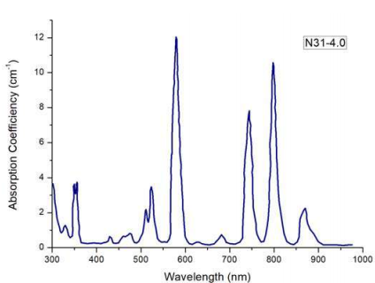
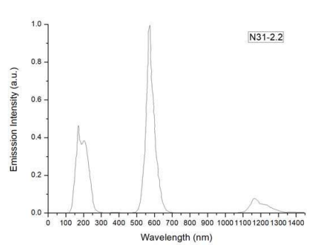
Source: https://www.samaterials.com/n31-nd-glass.html
Yttrium:

Holmium:

Thulium + Holmium:
Source: https://opg.optica.org/prj/fulltext.cfm?uri=prj-4-6-214&id=350876
Ytterbium:

Needless to say, I didn’t read sh1t.
I just found the first result and copy-pasted it.
Probably none of them are useful and in some cases it is said that it is about “luminescence”, which may or may not be related to laser emission.
On top of that, they use very, very specific types of glasses for each approach. Which may or may not work for sodium silicate.
It seems like the infrared wavelength that is “invisible to the atmosphere” is around 8000 nm to 15000 nm, and that is long-infrared and the light bulb emission is in the near infrared to the short infrared, unlike what I wrote before.
As you can guess, it seems I am as unreliable as the chatgpt’s AI, lol.
Something interesting that I found:
For some reason, nd:glass has only 40 to 60% of efficiency, but an optical fiber made of nd:glass is 92% efficient.
According to WebGPT, it is because the fiber has a super high surface area in which the light pumping has optimal transfer rate.
Even using sodium silicate for the neodymium oxide, I don’t think it would be practical to make a DIY optical fiber. I mean, you would need a really thin, long and super perfect hollow tube so you could cast the sodium silicate.
Besides, I don’t fully understand how fiber amplification works within lasers.
And according to this article that WebGPT linked to me, fiber lasers aren’t meant for high power outputs.
In any manner, the method used for optical fiber pumping is called a “cladding pump”, which I found on this website explaining it with images. It could be used as a basis for designing Nd:glass rod for lasers. Maybe this way will reach 90% efficiency.
I still don’t know what is the optimal size of laser rods based on the output power desired, pulse duration, pulse intensity etc.
But if I were to make an optical fiber, I would at least try to make something more like articulated optical pipes. Basically, the inner laser rods would be made with articulation in mind and all of the outside of the nd:glass rod would be reflective, then there would be a section for the pumping source and finally the outside layer.

This is a microscope articulated arm, but imagine the nd:glass parts shaped like this.

Other articulated pipes as an example.
Actually, I’m skeptical about that value. WebGPT is not the best source for anything, it could have shown a whatever value based on its generative bullshittering.
I still don't know what is the optimal size for laser rods based on the power output, but I found something interesting that may help:
While searching for conventional Nd:Yag laser rods, I saw this website were they say that the amount of power that can end up damaging the material is around 800 MW/cm².
A watt-second is equal to a joule-second, but a watt-hour is equal to 3600 joules, however, WebGPT told me that it would be around 800 joules per cm² for the laser rod.
In another website it says that their Nd:Yag lasers are a few dozen joules per cm² and then in other wavelengths they use the value of kilowatts per cm².
This website at least has some explanation to it, but I can't make heads of it.
"Pulsed Lasers
As previously stated, pulsed lasers typically induce a different type of damage to the optic than CW lasers. Pulsed lasers often do not heat the optic enough to damage it; instead, pulsed lasers produce strong electric fields capable of inducing dielectric breakdown in the material. Unfortunately, it can be very difficult to compare the LIDT specification of an optic to your laser. There are multiple regimes in which a pulsed laser can damage an optic and this is based on the laser's pulse length. The highlighted columns in the table below outline the relevant pulse lengths for our specified LIDT values.
Pulses shorter than 10^-9 s cannot be compared to our specified LIDT values with much reliability. In this ultra-short-pulse regime various mechanics, such as multiphoton-avalanche ionization, take over as the predominate damage mechanism [2]. In contrast, pulses between 10^-7 s and 10^-4 s may cause damage to an optic either because of dielectric breakdown or thermal effects. This means that both CW and pulsed damage thresholds must be compared to the laser beam to determine whether the optic is suitable for your application."
Another something that took my attention:
"Beam diameter is also important to know when comparing damage thresholds. While the LIDT, when expressed in units of J/cm², scales independently of spot size; large beam sizes are more likely to illuminate a larger number of defects which can lead to greater variances in the LIDT [4]. For data presented here, a <1 mm beam size was used to measure the LIDT. For beams sizes greater than 5 mm, the LIDT (J/cm2) will not scale independently of beam diameter due to the larger size beam exposing more defects"
Well, I need to compare a lot of things that probably needs super expensive instruments to measure and then make the thing.
... Like in the rest of the project logs, it would be easier to find a laser rod that already exists and then copy its dimensions with cheaper materials in order to approach its performance.

Disk lasers work like this, like a mirror, then maybe I can make a high power laser without the risk of melting/exploding it with so much power.
By the way, there is a thing called "Q-switch", which is basically a thing that pulsed lasers use to reflect the emitted laser multiple times in the gaining medium (like the laser rod) and then release it all at once in a stronger pulse.
Imagine it like one of those bouncing castles of some sort, but instead you add one above and one below, and every time you bounce you do an extra kick, adding more and more speed the longer you keep bouncing on both platforms.
And once you have significant speed, someone takes out the up bouncing castle and you go full ballistic into the sky.
That's kinda it.
But there are various ways you can do this q-switching thing, you can have a mechanical mirror that goes up and down with a motor for example.
The other example is of a saturable absorber/reflector, that only reflects the laser's light until a certain point.
You can do that using specific Dye lasers, crystals and the like.
But I really can't wrap my head around on how the electronic ones work.
The only one that ChatGPT explained to me as a crystal with a refractive index that can be changed based on the electricity you put into it, but I couldn't find whenever or not I can DIY such a thing.
The only way I could think of actually pulling this off would be if you instead of pumping the light directly to the laser medium, you would pump a smaller laser that then would point at another bigger laser medium.
So, since you don't have to worry about if the Q-switch would work or not with the full scale of the power input.
But that strongly depends on the type of laser medium you're using, if it is the Nd:glass laser with 50% of efficiency, you would only transmit half of half of your input power.
There is such a thing as a Plasma Mirror.
In the wikipedia article it is said that the plasma is made in fused silica (quartz) by applying a really intense laser pulse that will ionize the material.
I... Just don't understand how it is ionized or why it needs to be a laser that ionizes it. Wouldn't a kilovolt pulse ionize its surface and make plasma or something like that?
It can also be used for plasma lensing, but I don't know how to do neither.
What WebGPT said:
"Based on the search results, here are the key details for the energy and duration requirements of an ultrafast laser pulse to create a plasma mirror:
The laser pulse needs to have enough energy to convert the surface of a highly polished mirror into a highly reflective plasma. This is typically achieved with pulse energies in the range of a few millijoules [1].
The pulse duration should be in the femtosecond (10^-15 s) to picosecond (10^-12 s) timescale [1][2]. This ultrashort pulse duration is necessary to generate the high intensity required to create the plasma mirror.
Specifically, the search results mention that the researchers used a chain of plasma mirrors, where the first two mirrors were used to clean up the laser contrast by reflecting only the main ultrashort pulse and not the nanosecond-scale prepulse [2].
The third plasma mirror was then used as the basis for high-order harmonic generation, where the intense laser field drives the surface of the plasma, causing the electrons to oscillate at relativistic speeds [2].
In summary, the ultrafast laser pulse needs to have an energy of a few millijoules and a duration in the femtosecond to picosecond range in order to effectively create a plasma mirror for applications like high-order harmonic generation [1][2]."
I found this article here:
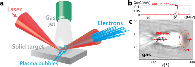
Source: https://link.springer.com/article/10.1140/epjs/s11734-023-00909-2
They always use the words "relativistic plasma mirror", and it is always about using the laser to focus on a really, really small point (as in the image).
So I'm guessing it is some "quantum-quacky-stuff" that makes it work.
Whatever it is the working method, it does look like some really complicated stuff that I honestly can't grasp.
Well, first: it seems like if you have a vacuum chamber with electrodes mirroring the shape of a lens, when making plasma, it will have similar properties to that of a conventional lens.
And yes, I know this is not what plasma lenses are normally about, but it is an easy work-around without too much complexity.
On top of that, I saw this experiment with lasers using water. If you have any material with a certain refractive index, depending on the angle, the material will act like a reflector, but not a mirror.
So, maybe, you could have a plasma chamber that acts as a reflector that directs the laser beam to an actual mirror in order to make the q-switch.
Accordingly to this simulation: https://phet.colorado.edu/sims/html/bending-light/latest/bending-light_all.html
I would need something with a refractive index of at least 1.3 (water) or 1.5 (glass) at an angle of 45 degrees from the light source in order to fully reflect it, or else the beam would just split in two, dividing the whole laser.
I asked chatgpt and it said that:
"So, the plasma density required to achieve a refractive index of 1.5 should be in the range of 10^9 to 10^12 cm^-3, with an angular frequency of 0.746ω.
An electron density of 1010 cm−310^{10} \text{ cm}^{-3}1010 cm−3 is 1014 m−310^{14} \text{ m}^{-3}1014 m−3. To give you a sense of scale, it's roughly:
10^10 electrons per cubic centimeter, which is a high density but not extreme. It's comparable to some conditions in lower-density plasmas found in laboratory settings.
Electron Density: Approximately 1.7 × 1 0 10 cm − 3 1.7×10 10 cm −3 to achieve a refractive index of 1.5.
Power Density: Typically in the range of 0.1 W/cm 2 0.1 W/cm 2 to 1 W/cm^2 1 W/cm^2 to maintain such an electron density in a low-pressure plasma system.
The exact power density will depend on the specifics of the plasma generation system and the conditions in your vacuum chamber.
I asked on quora if this is a big type of plasma or not, but I doubt I will receive any answer.
Also, about the rechargeable explosive pulsed power generator:
Needless to say: don’t try this at home, not even I will try this insanity.
I was having a little difficulty finding out how to calculate it, but after asking around it was said that I would need to just check the amount of joules needed to heat water.
So, you need 4.1 Joules to heat 1g of water to 1ºC.
Since I want to heat up 1 liter of water to 2000ºC in a steam explosion, I would supposedly need:
- 2000ºC - 25ºC (room temperature) = 1975 ºC
- 1975 x 4.1 = 8097.5 joules in total for 1 gram
- 1kg = 1000 grams = 8097.5 x 1000 = 8,097,500 joules
So, in order to output, let’s say, 30 megajoules of power, I would need around what?
“In your case, aluminium is said to have a specific heat of 0.90Jg∘C . So, what does that tell you? In order to increase the temperature of 1 g of aluminium by 1∘C , you need to provide it with 0.90 J of heat.”
So, taking a look at the specific heat list on wikipedia, the most promising materials to work with would be molten salt and aluminum.
Although molten salt melts at 220ºC and boils at 1200ºC while aluminum melts at 660ºC while it boils around 2200ºC.
Actually, the lithium would be the best, but I would need to use another fluid since water explosively reacts with lithium. But screw lithium.
So, assuming that I inject the water in the highest amount of injectors as possible in order to increase the efficiency of heat exchange as much as possible, reaching an efficiency of around 90%, I would need around:
- 2000ºC - 25ºC = 1975 ºC
- 1975 x 0.90 = 1777.5 joules
- 1777.5 joules x 1000 grams = 1,777,500 joules.
- 1kg of aluminum = 1,7 MJ
- 30 MJ / 1.7 MJ = 17.6 kg
Obviously, I doubt this would occur, for a lot of different reasons.
If the water steam absorbed 90% of this heat, the aluminum would immediately solidify since it lost 90% of its heat. So I’m willing to bet that the efficiency of heat transfer would be maximum 30% (even though ChatGPT says it would have 90% of efficiency, 99% even).
So I would need around 3.33 times more mass of aluminum, around 58.6kg. On top of that, Explosive pulsed power generators have really low efficiency, around 30% to 20%, so I would need even more water to absorb 3.33 times more heat.
So, 195kg of aluminum and 9 liters of water in total.
Not as portable than I thought, but more portable than a building sized capacitor bank.
For molten salt it would be:
- 1200 ºC - 25 ºC = 1175ºC
- 1175 x 1.56 = 1833 joules
- 1000 x 1833 = 1,833,000 joules per kg
- 30 / 1.8 = 16kg of molten salt
- 16kg x 3.33 of efficiency of heat transfer x 3.33 of efficiency of generator = 177kg in total.
But if I want to “just” have a pulse of 10 kilojoules, then I would need around 5.8 grams of molten aluminum reacting with around 11 grams of water, and 5.4 grams of molten salt to react with the same amount of water.
To separate the molten liquid from the steam, I would use a liquid vapor separator, like this one:

The steam would go through a radiator and turn back into liquid while the molten metal/salt would go back to the molten tank.
I did think of making the moving part being an air piston with an electromagnet inside of it, while the outer coil is the stator that catches the energy, the air piston being able to go back and forth a few times after the steam explosion.
This maybe would make the system slightly more efficient.
But I was wondering if the most efficient and portable option would be to make the moving part a turbine, just like in the flywheel systems. But google didn’t show anything similar to an explosive turbine pulsed generator, so I can’t say for sure if it would be efficient or practical.
I also thought of making the structure more similar to a magnetized target fusion reactor, lol.
Lithium and glycol (it doesn’t react with lithium, unlike water, and it has the same specific heat as water) would both be better options than the water+molten metal/salt, but lithium is highly toxic and dangerous to humans. But of course, if you are crazy enough to put an explosive pulsed power generator on your backpack, you wouldn’t mind the extra hazard. I bet the system would be 3 to 4 times lighter than the molten aluminum/salt.
If you use the hydrolysis of water to generate hydrogen and oxygen, then the weight might become more acceptable.
For example, 1 liter of water converted into 900 grams of oxygen or 629,8 liters and 100 grams of hydrogen or 1194 liters of hydrogen, you would need around 13.2 MJ of energy, and assuming 100 bar (or 10 MPa) gas tanks, you would need a tank of at least 11 liters of hydrogen and another with 6 liters of oxygen for that.
However, the efficiency of hydrolysis is around 70% and the efficiency of the explosive driven pulsed power generator is 30%, you would need 3.33 times more liquid/gas, for the same 13.2 megajoules, totalling 82.5 liters of hydrogen at 10 MPa and 45 liters of oxygen at 10 MPa for the 30 megajoule threshold.
I just don’t know how you would detonate around 8250+ liters of hydrogen and 4500+ liters of oxygen at same time in this generator.
Just now I remembered that you would either need a really powerful pump for that, or make the hydrolysis in a really tough gas tank.
“It's a question I had also and if I remember well I read somewhere that this process is pressure insensitive, which makes no sense to me ! But from what I understand it seems to be the case, and here is an application of this similar to your idea of high pressure ocean water electrolysis : http://en.wikipedia.org/wiki/High_pressure_electrolysis Does it make sense ?”
Source: https://www.physicsforums.com/threads/effect-of-pressure-on-electrolysis-of-water.179504/
I was thinking here: this is really a convoluted process of generating electric pulses, why not just use the fuel directly?
Well, the only problem is that you would need an air compressor and an air tank.
And these have terrible efficiency, or maybe not, I mean, you would need a little compressor to get just the right amount of air.
Also, I said that you could use a turbine flywheel hybrid, but I don't know how simple that would be.
We are talking about a detonation engine, not a conventional turbine. You would need really precise calculations and really thick blades to avoid it being absolutely destroyed.
I had the thought of using a dual way counter rotating turbine, just like steam turbines, where they convert the extreme pressure and speed of steam into rotational motion.
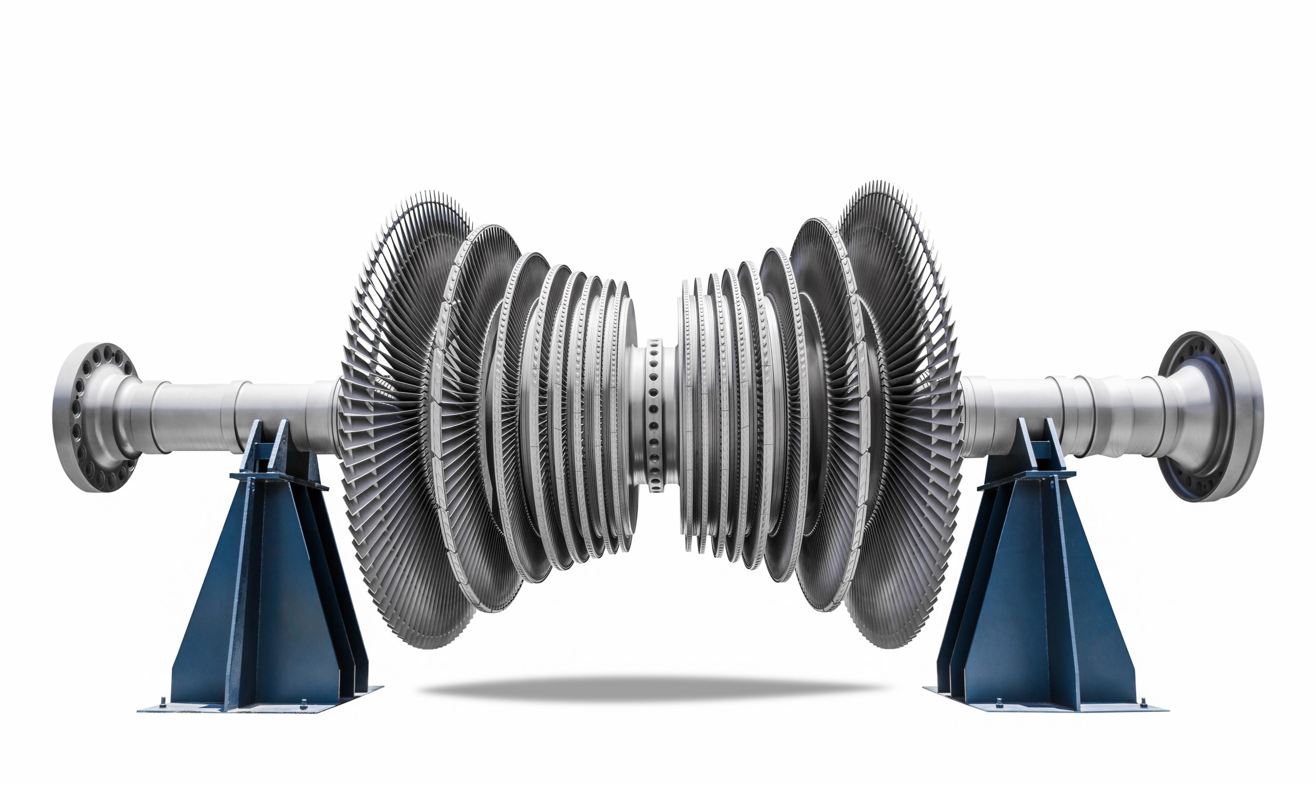
The stator (yes, they have stators) always takes some amount of efficiency out of the equation, so, for absolutely maximum efficiency, it could be interesting to make what would be stators into counter rotating turbine blades also.
Making the entire counter rotating turbine would be really complex and difficult, but since the electromagnetic bearing would also be the generator and shaft, then it would be "easier" to make every disk rotate independetly.
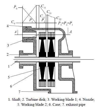
Of course, I'm thinking of the blades to be as thick as a screw thread because of the explosion, although, the more it travels through the blades, the less powerful the wave would be.
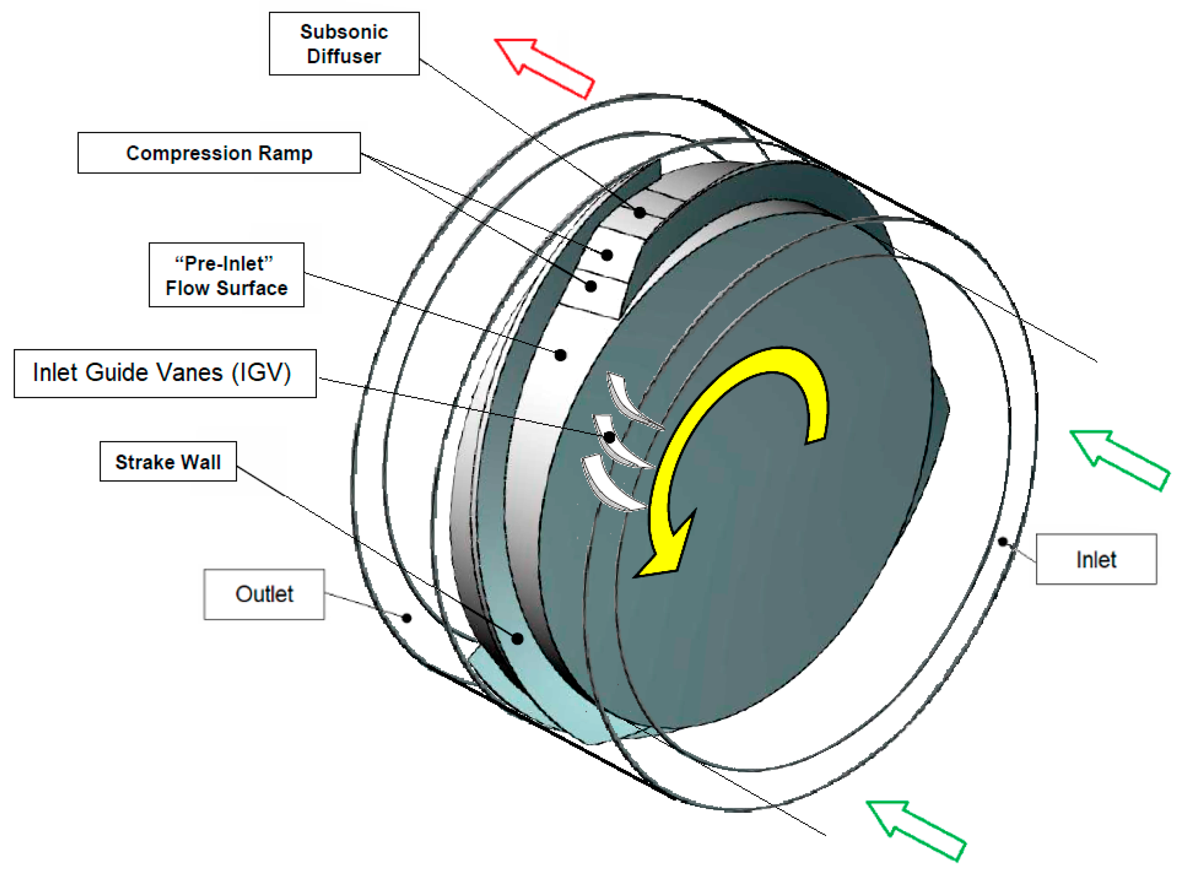
Source: https://www.mdpi.com/1996-1073/15/24/9353
Just now crossed my mind that you could actually use steam instead of coal or hydrolysis to power this thing, heating steam electrically is 90% efficient.
Discussions
Become a Hackaday.io Member
Create an account to leave a comment. Already have an account? Log In.
hey have you considered an EVA (from.. evangelion...) style umbilical cord design for the power supply? that is... not make a power supply and rather make a flexible enough cable so you can just use the grid/cheap coal/gas generator, without worrying about size?
If anything, it would be one hell of a prototype
Are you sure? yes | no
I was thinking of doing it for a prototype, but I'm having the basics of power supply already sorted out for future me.
Are you sure? yes | no