ChatGPT:
“Fluxes are essential in aluminum alloy processing, particularly for refining molten aluminum by removing impurities and enhancing the metal's quality. The effects of specific fluxes—such as Sodium Fluoride (NaF), Potassium Fluoride (KF), Boric Acid (H₃BO₃), and Chlorides—on molten Aluminum 7075 are as follows:
Sodium Fluoride (NaF): NaF is commonly used in flux formulations for aluminum refining. It aids in removing oxide inclusions and degassing the melt, thereby improving the alloy's quality. However, the residual sodium content from NaF fluxes can be detrimental, potentially leading to issues like hot shortness in aluminum alloys. Therefore, controlling the sodium levels is crucial.
Potassium Fluoride (KF): KF, similar to NaF, is utilized in flux mixtures for aluminum refining. It contributes to the removal of oxide inclusions and assists in degassing the melt. The specific impact of KF on Aluminum 7075 would depend on its concentration and the overall composition of the flux mixture.
Boric Acid (H₃BO₃): Boric Acid is not typically used as a flux in aluminum refining. Its role in aluminum processing is limited, and it is not commonly included in flux formulations for molten aluminum.
Chlorides: Chloride salts, such as Sodium Chloride (NaCl) and Potassium Chloride (KCl), are frequently used in flux compositions for aluminum refining. They help in removing impurities and oxides from the melt. The effectiveness of chloride-based fluxes depends on their specific composition and the refining conditions. For instance, a study designed fluxes with NaCl and KCl, among other components, to refine aluminum alloys effectively.
In summary, while NaF and KF are beneficial in flux formulations for refining molten Aluminum 7075, Boric Acid is not typically used for this purpose. Chloride salts are also effective fluxing agents, with their performance influenced by their specific composition and the refining conditions”
Metal matrix composite - Wikipedia
Tribological behaviour of aluminum alloy (AA7075) based hybrid composites
Microstructure Control and Performance Evolution of Aluminum Alloy 7075 by Nano-Treating - PMC
“The results demonstrated that the addition of ZrH2 particles allowed the grains to be clearly refined, and that maximum tensile strength was above 330 MPa, which represents promising performance among the reported LMD-fabricated Al alloys.”
Preparation and characterization of alumina–iron cermets by hot-pressing of nanocomposite powders
Metal Matrix Composites | Encyclopedia MDPI
(PDF) Spark Plasma Sintering and Characterization of Al-TiB2 Composites
Study of Microstructural and Mechanical Properties of Stir Cast Al (SiC-Mg-TiFe) Composite
Physio-mechanical properties of aluminium metal matrix composites reinforced with Al2O3 and SiC
(PDF) A comprehensive review on stir cast Al-SiC composite
mechanical behavior of an alumina fiber reinforced aluminum wire in tension and after axial torsion
Study of Microstructural and Mechanical Properties of Stir Cast Al (SiC-Mg-TiFe) Composite
Metal Matrix Composites: Classification, Manufacturing, and Application
Physio-mechanical properties of aluminium metal matrix composites reinforced with Al2O3 and SiC
(PDF) Depiction of Aluminum-Fly ash hybrid Composites
I was avoiding using steel smelting in general because it is heavier than aluminum and has a higher melting point (more or less 1400ºC), and thus, I wouldn’t be able to make a mold anyway.
However, just now I went looking for DIY steel mold injection and essentially, they use “greensand”. Which is just a mix of sand and oxides like alumina with a binder.
Even though sodium silicate (and other high temperature binders like plaster of paris [sellers say it can only withstand up to 1000ºC, but sources says it can go up to 1500ºC]) melt at maximum 1000ºC to 1200ºC, the sand melts at 1700ºC and the mold itself will survive due to the fact that it will be at a colder temperature than the molten steel while the sand/oxide powders will work as insulators. Essentially, it will be like casting wax in an ice mold.
Metal Casting Play Sand - TKOR Shows You How To Make Green Sand, Sand Casting And More!
How to Make Greensand For Casting And Greensand Molds
DIY Metal Casting Sand from Kitty Litter - Green Sand
Metal Casting at Home Part 78 Full Details. Sand Preparation, Moulding ,Cores, Casting.
Commercial VS homemade molding sand
How to make a sand mold for casting metal
Mastering Metal Casting: Step-by-Step Guide | Foundry Mastery Series | Art of Making
You can still melt the steel with a microwave oven, but you will need to buy conventional crucibles made out of some high melting temperature material, such as graphite, silicon carbide, alumina etc.
Forged steel is said to be around 30% stronger than cast steel because its grain structure is more uniform, while in cast it is random.
Intro to heat treatment of steel (hardening and tempering)
Heat treatment suggested by ChatGPT:
“1. Annealing
Purpose: Both approaches start with annealing to relieve stress and improve workability, a fundamental step for cast stainless steel.
Temperature and Duration: Your source suggests a temperature slightly higher (1040°C) for full annealing, which is suitable for large cast pieces. If grain refinement is crucial, the lower temperature of 1010°C helps control grain growth.
2. Hardening
Purpose: Hardening is mainly useful for martensitic stainless steels, which benefit from quenching to form a martensitic structure. However, for austenitic or ferritic grades, hardening isn’t always appropriate and may not result in increased strength.
Temperature: The temperature (980-1010°C) aligns well with martensitic hardening.
Cooling: Rapid quenching helps lock in the martensitic phase for hardness but can increase brittleness, which later tempering should address.
3. Tempering
Purpose: Tempering reduces brittleness in martensitic stainless steel. Your suggestion’s lower temperature range (200-510°C) is ideal, allowing a balance between strength and toughness.
4. Aging/Precipitation Hardening
Purpose: This step is specifically beneficial for precipitation-hardenable stainless steels, like 17-4 PH (a martensitic-austenitic stainless alloy).
Temperature and Duration: Holding for 4-8 hours at 480-620°C, as suggested, will optimize strength through precipitation hardening.
5. Stress Relieving
Purpose: Reduces residual stresses from prior processing, especially for complex parts where stability or corrosion resistance is critical.
Temperature: The range (400-925°C) is broad, and it can be tailored based on specific grade requirements. Lower temperatures are better for minimizing distortion.
Stress relieving is an optional but useful step to ensure dimensional stability and corrosion resistance, especially after significant heat treatments.
Best Approach:
For martensitic stainless steel: Follow the full suggested sequence (annealing, hardening, tempering, aging, stress relieving) to optimize both strength and toughness.
For austenitic stainless steel: The original approach (solution annealing, aging) is sufficient since austenitic grades do not benefit from hardening or tempering.”
If you just want to go for steel metal foam instead of a lattice structure, you can check the list of foaming agents that I linked earlier.
(PDF) Atomistic insights into metal hardening
DIY Steel Melter (HIGH CURRENT ELECTRICITY HACK)
5000 DEGREE electric arcs | High Voltage |
The Magic Of Citric Acid: How To Passivate In-house
Proto Tech Tip - Chemical Conversion Coating VS Passivation
It's not ruined, trust the process! (Rust Bluing)
Best Way To Blue Steel? Cold Blue, Hot Blue or Rust Bluing.
Bluing Steel Hot & Cold - Rust Protection - Easy To Follow DIY Guide #bluesteel #rustprotection
3D model of electrical system, programming and control panel:
I think I should at least attempt to design a Dashboard/HUD/control panel for the mech, including electronic systems (with the feedback sensors), programs, and the feedback touch system that allows the user to control the mech.
Obviously, the control panel will be changed to be relevant to control the mech’s systems, but most of the dashboards are for cars instead.
And remember, I’m no engineer, no electrician, no programmer, so I will just design the programs, systems and controls in a way that I can easily understand.
I just saw this post on reddit, and I thought to myself: “Can I make a mech that is idiot-proof? Can the idiot-proof design win against my own stupidity?”
What Was Idiot Proof Before an Employee Proved Otherwise?
https://www.youtube.com/shorts/KyzXg7eUoAE?feature=share
I also need to remember to add safety features, like emergency manual disconnecting levers/cables in case anything stops working as intended.
There is another thing, I said that I would use an arduino and/or even redundant arduino PCBs for servo motors as the central program.
However, I was interested in making an electromechanical copy that can be built from scratch instead of arduino driver boards.
I have no idea how I would do that, or even if it would be practical to do that.
The Z3 was a relay powered electromechanical computer that worked at maximum 10 hertz and only had a memory of 64 words each consisting of 22 bits and weighted 2,200 lbs.
The only practical way a servo driver could be built from scratch in a practical manner would only be done if it was a stepper motor of some kind.
So you could rotate the rotary relay with the strength of your body alone and the mech would work accordingly.
ELECTROMECHANICAL LIGHT CHASER OF DOOM - DIY Build
The Weird Story Of Electromechanical Memory - 40 bits of the stuff!
(examples of rotary relays)
Source: How does a Stepper Motor work?
… But there wouldn’t be any force feedback, position feedback etc.
Or maybe not?
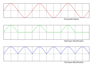
Source: https://mathematicalmysteries.org/sine-wave/
Ele electrical signals and electric waves going to the motors are sine waves from a circle.
So, if I use a variable scotch yoke mechanism, I could control the 3 phases of the motor mechanically.
Ele electrical signals and electric waves going to the motors are sine waves from a circle.
So, if I use a variable scotch yoke mechanism, I could control the 3 phases of the motor mechanically.
Source: https://www.engineeringcommons.org/mechanisms
The variation would be controlled by the pilot with the movement of their body, the intensity and speed.
A good way of powering these servo-scotch yokes would be either using hydraulics and/or brushed motors.
I mean, I don’t actually need to make a scotch-yoke mechanism literally, just a electromechanical rheostat that can change the speed of opening, closing, changing the amperage from 0 to 500 and reverting the flow of electricity.
It could be a linear rheostat in a pneumatic tube, it could be a rotary rheostat hydraulically actuated or anything of the manner.
If the actuator rotates too fast, and thus, requires an electromechanical rheostat to rotate just as fast, or you just want to avoid any kind of friction, then maybe you could use a transformer-rheostat hybrid. The Transformer-rheostat hybrid would be two sets of coil like any transformer, but they would be organized like a rheostat, where the bigger the distance from the input to output, the bigger the electrical resistance.
Or you could make an electrically conductive bearing that rolls over a conductive surface…
Electrically charged bearing wear and pitting test | Electrical conductive grease test
The encoder, on the other hand, would need to mirror the movement of the sine wave mechanism and automatically and mechanically approximate one to the other.
If the rate at which mechanism mirrors the position of the actuator can also be adjusted, then you could simulate both spring motion and damping motion.
ChatGPT suggested (yes, I always ask chatgpt because all of my friends cannot care less for mechs) that I should use a mechanical follower for the encoder and/or variable transformers.
Linear variable differential transformer - Wikipedia
LVDT - Linear Variable Differential Transformer or Transducer Working
Basics of the Linear Variable Differential Transformer (LVDT)
What is a LVDT (Linear Variable Differential Transformer)?
Rotary variable differential transformer - Wikipedia
RVDT (Rotary Variable Differential Transformer)
RVDT Rotary Variable Differential Transformer
Although ChatGPT was just suggesting an electric encoder, I do think this could work as a feedback position control system.
The output of the variable differential transformer could power an electromagnet gear system connected to a rheostat. The more it went close to a pole, the stronger it would move away from it due to the strength of the electromagnet field increasing.

Source: Planetary Magnetic Gear Box, Working Prototype - GreenLabs
One disk would be the sine wave generator (the scotch yoke mechanism), and the other disk would be connected to the rheostat between the electrical connection system and the direct motion to the motor.
The more it encountered resistance, the more it would be rotated to a side, the more the more it would decrease the electrical resistance, increasing the strength of the electromagnetic field.
Obviously, you would need to build in a thermal switch to avoid overheating of the system.
I also need to remember to add batteries to heat up the power source (helium engine or molten carbonate) before it starts to generate power.
Also, I actually wanted to give another try on a temporary power source for the fluctuations in the mech.
… Buuuut it seems it won’t work as well as I intended, you see, the fluctuations in the range of a few kilowatts won’t be that much of a problem, but the fluctuations on the range of 100 kilowatt and 300 kilowatts (or more) will definitely be.
Watt seconds = Joule seconds.
Every battery and capacitor has a discharge rate and a maximum storage value.
AA batteries have 10,000 joules stored into them, but can only output 3 watts/joules per second at best.
Capacitor banks (or single capacitors) and battery banks simply cannot keep up with that.
I would need to use that idea I had about the rechargeable Explosively pumped flux compression generator for pulsed power generation, where I would use hydrolysis or just direct fuel+air dust explosion to generate a repeatable detonation to power it up. According to ChatGPT, you would need 0.044 liters of water to convert into 58.8 liters of hydrogen and 29.5 liters of oxygen to achieve 700,000 joules.
Maybe a conventional flywheel energy storage/kinetic capacitor would be safer, and I think I misread it in earlier project logs:
Flywheel energy storage - Wikipedia
Compensated pulsed alternator - Wikipedia
It can reach a density of 500,000 joules per kilogram of weight, but I bet I would only reach around 50 kilojoules.
100 Amp Variable Voltage Transformer
Mechanical inverter/transformer - 3V to 700V
DIY remote controller for robots (Arduino + nRF24L01)
Virtual Reality #2 | Game Controller Interaction | James Bruton
MAKE THIS BUTTON BOX | 32 FUNCTION w ENCODERS
Building a Touchscreen Smart Robot Remote
Building a Camera Motion Control Rig
Building a DSM2 R/C Transmitter with Arduino
Home Automation 32CH Distribution Board DIY Smart Home IOT Project 2020
How to Design & Build an Industrial Control Panel - at AutomationDirect
Remote control panel V3 for Onefinity / Buildbotics CNC controller
Introduction to UL 508A Industrial Electrical Control Panels with PLC
Zero Delay USB Arcade Encoder | Review & Playtest
Making Analog Gauges - Home Flight Simulator
Building a Standby Compass- (and how I finish 3D prints) - Home Flight Simulator
The Caution Panel (with a Typo) - A10C Warthog Simulator
How to Customize Your '03-'07 GM Gauge Cluster in 12 Minutes!
Harbor Freight DIY Solar Generator
DIY Solar Generator - Save Thousands by Building Your Own
How to Build a DIY Solar Generator Setup - Complete Review - Beginner Friendly - 12V
DIY Solar Generator! 1536Wh Portable Power Station Lithium LiFePO4 HOW TO
DIY Raspberry Pi Racecar Dashboard: The Ultimate Guide
Making an All-Metal Car Dashboard
DIY ARDUINO RPM REV TACHO SIM HUB DASH
Homemade Electric Buggy, Ep 8: Dashboard & Charge Port
Arduino Car Cluster with OLED Display (Dashboard, gauges, controls, SSD1306, u8glib)
3D Printed Dashboard for a C10!
Finishing my 3D Printed Gauge Cluster for SEMA!
Designing a 3D Printed Center Console From Scratch
Nova AC Delete Gauge Cluster by jwilhite - Thingiverse
Evo X AEM X-Series Gauge Cluster Mounts by mpbiv421 | Download free STL model | Printables.com
https://www.thingiverse.com/thing:5775743
How To - 3D Design a Custom Gauge Cluster with TinkerCAD
How this Active Gyroscope Balances
What is a Reed Relay? from Pickering Electronics
COMO FAZER INTERRUPTORES MAGNÉTICOS (Reed Switch) - FÁCIL !!!
Beginner Electronics - 1 - Introduction (updated)
Water Level Indicator with LED - PCB Tutorial
Make plastic printed circuits with a standard laser cutter
Underwater laser cutting and silver sintering to make ceramic circuit boards
Atomic Layer Deposition of copper - If you like sputtering, you'll love this!
Ultrasonic soldering bonds glass, titanium, stainless steel, ceramics, tungsten, nichrome...
Clear flexible printed circuits - first success
The book every electronics nerd should own #shorts - YouTube
Building an Electric Bike Without Electronics (mechanical control for electric motor with reed relay)
Vintage electrical tech - Weston Sensitrol Relay
Explanation of how kilowatt-hour meters work (electromechanical)
HOW TO CREATE A CPU IN AN FPGA - Part 2 - Registers
Software on Paper - 1985 Cauzin Softstrip
https://www.youtube.com/shorts/DxVK53ap1eY
AH-64 TEDAC unit built - Controller Questions and Bugs - ED Forums
DIY Ergonomic Game Pad Lends A Hand | Hackaday
Svalboard - Ultimate Ergo Keyboard Build Guide (DIY)
I turned my OLD CONTROLLER into the ULTIMATE KEYPAD!
THE BEST OF BOTH WORLDS | Mouse Pro Controller V5
3D Printed Helicopter Collective for MSFS2020, Xplane & DCS
3D Printing Metal In Mid Air | Hackaday
2332 Relays, Transistors, Memory And Counting
What are the Types of Switches? (Electrical & Mechanical Switches)
Attaching any Switch or Button to Arduino Microcontrollers!
7 FATAL Wiring Mistakes Most DIYers Don't Know They Are Making | Most Are Guilty of 3
2333 Making Oscillators From Relays
Fixing the Full Bridge Rectifier’s Big Flaw - Active Power Factor Correction
Every Component of a Switch Mode Power Supply Explained
What Kind of Wire is That? - YouTube
How Power Transformers work ? | Epic 3D Animation #transformers
Buchholz Relay: The Power of Simple but Effective Engineering | 3D Animation #transformers
Making custom circuitry PCB and housing for vibration motors
How I Designed 3D-Printed Mods for My Vintage Toyota KE25
ESP32 chip(s) Explained - in under 500 seconds!
I made the SMALLEST STM32 board (ESP32 can’t compete!)
How to Prevent Lightning Damage to The Generator Set?
(PDF) FFS: LIGHTNING STRIKE PROTECTION OF RADOMES – AN OVERVIEW
Static De-shocker Wand by alany - Thingiverse
11kV lightning arrestor and exploding disconnecter.
EMP BUSTER !! EMP SHUNT... Lightning arrestor, DIY CME Arrestor ! Part 1
The Best Protection for your Circuit is NOT a Fuse!.....but a Resettable Fuse? EB#54
External lightning protection Vers 02
Things you should know about fuses. (including a 15kV one)
100 Amp Variable Voltage Transformer
I do intend on making this hydrolysis powered torch to weld/solder the aluminum wires/cables together because I don’t trust that the Tin solder will be able to handle the energies involved in this system.
But in the end I will need to make connectors/plugs for safety and modularity.
On top of that, I will also model the Reed Relays.
Adelita + Analco + Bandui Lab :: Behance
New Ultra-thin e-skin that can Turn your Skin into a Digital Display
Building circuits the hard way. An introduction to freeform electronics
Aluminum PCBs: A Comprehensive Guide to Help You Understand
DIY PCBs At Home (Single Sided Presensitized)
I Built an OCTAHEDRON Lamp, Cause Why Not
Now the electrical Connectors:
I’m from the future and basically, I wrote this section after the slip rings/cooling jackets, but I added this first because it makes more sense to model the electrical connectors before the slip ring connectors.
But essentially, I will use an air cooler using ambient air/nitrogen gas in the air to cool down the system to -70ºC, which is safer than using liquid cooling.
And said air cooling channels will go through the connectors both for safety and space economy, since the connectors are the parts that face the most heat from inefficiencies.
How Electricity Works - for visual learners How Electricity Actually Works (relevant)
Again, I’m no engineer and every video I list here just shows how bad of an idea it is to mess with electricity at such absurd wattages.
You can die. You’ve been warned.
A few examples to base myself on:
Amphenol ICC - OCTIS™ Power Cable Assembly
Amphenol Surlok high power quick disconnects!
Entertainment industry 400A powersafe connectors. (this one is a “power safe” 400 amp connector, I intend on using 500 amps)
Camlock Connectors (this one shows the dangers and problems involved with cables and connectors, even copper connectors build up heat up to hundreds of degrees (fahrenheit or not, it doesn’t matter), how to identify the possible problems and how to change it)
Entertainment industry connectors.
How Pros Use Crimp Connectors, how to use crimp connectors, the right way
My favourite industrial connector (Ceeform).
Electrification Charging Solutions & High Voltage Connectors
How to make High voltage cable joint
T-body Connector Assembly - Hubbell Power Systems
High Voltage Connector With HVIL Funciton | Renhotec Technology
How To Insert Wire Into Insulated Power Connector
High Power Connectors for Automotive Use with Wiring Products
Instalacion de Accesorios MEDIA TENSION SUBTERRANEA CFE (I liked this one too, I think it would be interesting to have a connector that only becomes “connectable” when you press a lever and releases a lock, then you connect to what you want and then releases the lever again)
- 3D modeling the connectors:
- They need to be waterproof both when connected and disconnected.
- Fireproof (or at least fire resistant).
- They need to be safe and easy to disengage when something in the system goes wrong.
- They need to allow good heat transfer for the cooling channels to avoid overheating, melting and/or fire.
- Also, I need to make embedded connectors specifically to be embedded in the actuator’s resin.
Low Leakage Cryogenic Disconnects | 3D CAD Model Library | GrabCAD
I found this low-leakage cryogenic connector, dunno if it would be interesting to keep the connectors inside the nitrogen coolant tubes/hoses, or the nitrogen coolant hoses inside of the connectors.
I’ve decided: I will make the coolant go through the connectors, that’s the spot where heat concentrates.
- 3D model the coolant connectors on the electrical connectors themselves. I can’t really 3D model the thermally insulated tubes, but I can make a 3D mockup of them.
- Optional: 3D model clippers to keep the cables organized, but since there are off-the-shelf options, I don’t think it will be necessary.
- Although I can’t 3D model it, it could be interesting having thermometers along the cables/connectors and tear sensors in case something damages the insulation layers.
“Tear-sensors” make it look like it's some high-tech stuff, but in reality it is just a bunch of conventional cables with a few watts running through them. If they become damaged, they will stop transmitting energy, which in turn will show you in the dashboard/HUI that something is wrong.
5 Motorcycle Electrical Tips from a Pro
Underground cable fault detection | how to make underground cable fault detection system
DIY Tripwire security alarm device using a transistor / Cut wire alarm / Wire Break Alarm
Home Made Wireless Phase Tester | Break Wire Sensor | #DIY
This could also have an automatic circuit break.
10 Common Mistakes DIYers Make In Circuit Breaker Boxes
Why Circuit Breakers DON'T Protect People (electric shocks)
One Circuit Breaker To Rule Them All!
Circuit Breaker Basics - How do they work?
Why are miniature circuit breakers (MCB) so important? |3D Animation..
Understanding PV Solar Circuit Breakers - DC vs. AC - why they are different #solar #diy
As much as I’d like to have commercial 500 amp circuit breakers, they cost thousands of bucks. So I will need to design them too.
THis also includes busbars, buspanels, ground fault circuit interrupter (it detects if the ground has an external connection, like a human, so it interrupts the flow) and transfer switches.
120V 240V Electricity explained - Split phase 3 wire electrician
GFCI breaker basics - Ground fault circuit interrupter how it works
AFCI vs GFCI: What's The Difference and Why You Should Care
Busbar Trunking Installation | E-Line KX | EAE Elektrik
How To Choose Between A Transfer Switch Vs Interlock Kit With Power Inlet Box
AC Polarity Explained - Electricity 101
What are Tamper Resistant Receptacles (TRR)?
Gas-insulated switchgear: safe operation
You can (and you should) ignore my 3D model connector and just buy the reliable and safe connectors from the market.
I will call these DIY connectors “Anhangá”, because they are a f*cking death trap.
You know, I’m starting to think that the safest approach would be to make all the contactors a 1:1 transformer.
This way you could make contacts that don’t need to directly connect anything conductive with anything, the connection would be electromagnetic.
Delta-wye transformer - Wikipedia.
How does a Transformer work - Working Principle electrical engineering
How 3 Phase Transformers Work – why we need them
TRANSFORMERS - What They Are, How They Work, How Electricians Size Them
How distribution transformer works | structure of distribution transformer
https://br.pinterest.com/pin/226657793742104467/
I would need a lot of diodes/full bridge rectifiers, they are actually kinda cheap in the 100 amp… For a single full bridge rectifier. These are normally
In any manner, although the connectors will be transformers, the bus panel/ESC won’t.
And now that I think about it, since the stator-rotors don’t have permanent magnets and are mirrored stators always facing either the opposite pole or the same pole, it doesn’t matter if it is AC or DC.
And since both are at the same frequency and weight, then I don’t need rectifiers.
So this makes the motors an “Direct and Alternating Current Hybrid Direct Drive Double Wound Air Core Axial Flux Brushless Servo Torque Motor” (DACHDDDWACAFBSTM). What a mouthful… Or you could just call it a “Xangô-motor” :3
Just now I found out about pulsed DC, and they can work just as well as AC to transfer electricity through induction.
Can pulsating DC current be transformed? - Physics Stack Exchange
Now I will make the slip rings and cooling jacket
Do I really need to make the electrical slip rings since the connectors are transformers that can rotate on their own axis?
Actually, yes, I can’t pass multiple connectors through a rotary axis without interfering with each other.
The slip-rings will be used both for the electrical cables and for the bags that will be used as the casing/shell.


Something like this.
- 3D modeling the slip ring:
- They need to be leak proof both for gasses and liquids.
- They need to be modular so you can either use them as sealants in the cooling bags or electrical connectors for the actuators.
- They also need to fit into the electrical connectors previously modeled.
I will make sure to use a really strong combination of materials, but in the end I will have to use the structure as the final protection shell for the robot.
For now, the idea for the “cooling jacket” is to embed a nylon/polyester cloth with silicone rubber for both insulation and impermeability.
Now that we are on the subject of cooling, my initial idea was to use either deionized water, silicon oil, mineral oil, glycol or commercial coolants for cooling the system down.
However, that will add weight and cost to the project.
And since in the Helium Turbine 3D model section I talked about the helium can be replaced by nitrogen, I think it is a good idea to do that to the system (yes, I wrote that section before finishing the project, which can be confusing to read).
Or you could simply use ambient air if you take out humidity and dust as much as possible.
After all, it is:
Nitrogen 78.084>#/b###, Oxygen 20.946>#/b###, Argon 0.934% and Carbon dioxide 0.042%.
If you really want to use pure nitrogen without buying it, you can use pure iron/copper powder as an oxygen scrubber. If they saturate, you can use heat and hydrogen from hydrolysis to revert it.
The idea is to use nitrogen gas as the coolant… But since we are in this subject, I do think that this means that the idea of reducing the temperature of the system to -70ºc will become safer and viable now.
However, there is still the risk of frostbite and asphyxiation when dealing with gaseous coolants at -70ºC. Especially if you are working with a pressurized system, which I won’t.
With that in mind, the aluminum wires at -70ºC would have the same resistivity of copper at ambient temperature.
By the way, silicone rubber and HDPE can still be flexible at -70ºC, but they become more rigid. Their ”glassy” temperature is around -120ºC and -110ºC respectively. You would need to take that into consideration when building.
I couldn’t find much information on the effect of low temperatures on enamel insulation for wires, which may or may not fail at these specific conditions.
Cryogenic Insulation Materials | Low Temperature Storage, Efficiency
it seems like you would need to either use epoxy/polyurethane specific for electrical insulation (which is kinda expensive), silicone rubber or anodised aluminum wire.
Epoxy resin does not survive the -70ºC ambient, but there are specific epoxy resins that can. I couldn’t find them however… When I search for low temperature epoxies google only shows results talking about its curing time, not its structural integrity.
Selected Application- Cryogenic Temperature and Epoxies
This document from NASA says that most epoxies can survive up to -273ºC.
Testing Tensile and Shear Epoxy Strength at Cryogenic Temperatures
Another document testing them at 86ºK (-187ºC).
Progressive Failure Analysis of Glass/Epoxy Composites at Low Temperatures | IntechOpen
These articles show that the performance of epoxy resins doesn’t change much at lower temperatures, in some cases it actually gets a little bit stronger.
I don’t think I can make a 3D model for the cooling bags nor the insulated cooling tubes in specific, I can only direct you on how to do it (thus the video-tutorials).
DIY tube insulation and thermal bags insulation:
Genius or gimmick? ✂️ - r/GadgetVerse on Reddit
Great Thermo Bag from Bottles | Life hack: how to make a thermal bag with your own hands
DIY Insulated Box For Food Runner
Underground Insulated PEX For Your Outdoor Furnace | Expert Advice on Lowest Heat Loss (Best Value)
Tube insulation, piping with sprayfoam
Tank Insulation | How It Works (this one isn’t exactly DIY, but it can be helpful)
How to insulate your plumbing lines on a DIY Cold Plunge | Tutorial
You could also add acoustic insulation to the actuators, because this thing will be really noisy once it starts working (example, and this one is maybe 10 to 100 times weaker than the mech actuators).
How To Make Your Own Acoustic Panels - DIY Professional Acoustic Treatment for Home Studio
How Does Noise-Cancelling Tape Work?
DIY $10 Acoustic Isolation Box
DIY Speakers and Acoustic Panels
What material is the best for soundproofing?
Active acoustic cancellation is also interesting, but you would need DIY speakers: World’s Best Speakers!
Impossible Active Audio Noise Cancelling by Muzo
I would also suggest adding styrofoam particles and/or other thermal insulators into the cooling bags/tubes construction, like polyurethane or aerogel blankets (surprisingly enough, these are already accessible in the market and are surprisingly cheap, but you need to check if they have mineral wool in then, it is dangerous to inhale).
There is also nanowood/wood aerogel, which is essentially the precursor for densified wood.
This is nano wood—an ecofriendly alternative to styrofoam insulation
It works as a thermal insulator, but you could also use it as a foam.

You can even make it into an airloy.
Also, I think I will add a metal wire mesh both for structural protection and faraday cage (electric/electromagnetic protection).
The mech will be using motherfricking 300,000 watts of energy. I can only imagine what would happen during a storm.
Generator: DON'T Forget To Do THIS or You'll FRY Your Sensitive Electronics!
Faraday Cage demonstration. - YouTube
CABLING BASICS – Wavelength Electronics
These links below are about preventing surges and grounding wires in electric systems, and yes, mobile electrical systems such as the ones in planes, cars and helicopters are grounded, their metal chassis is used as the ground.
How Are Plane Electronics Grounded?
Does Current Flow on the Neutral?
How to Fix Electrical Problems in Your Car (Ground Fault)
💬 Why is good grounding important? | TECHNICALLY SPEAKING
Avoid electric shock getting out of a car!
How Static Electricity is Dissipated
- Actually 3D modeling the slip rings and a mockup of the cooling bags, coolant tubes and ground wires:
Power Sources:
I have a few considerations for power sources, in all of them it is taken into consideration the necessity of using wood/biomatter as the fuel.
Thus, it would be required for all options to have a wood-chipper, a fuel reformer and maybe a fuel synthesizer.
The fuel reformer would transform wood/biomatter into syngas, a mixture of carbon monoxide and hydrogen gas. The fuel synthesizer would transform this syngas into other types of fuels, gasoline, diesel, methanol etc. However, I say “maybe” because the heat input (800ºC to 1000ºC) used to reform the fuel would be lost during the process, thus, further reducing the efficiency of the overall system.
ChatGPT:
“Syngas, a mixture primarily composed of hydrogen (H₂) and carbon monoxide (CO), serves as a versatile feedstock for producing various fuels through different conversion processes. The primary fuels that can be synthesized from syngas include:
Methanol: Syngas can be converted into methanol, which is a valuable chemical feedstock and can also be used as a fuel or fuel additive. Biomass in a petrochemical world - PMC
Synthetic Natural Gas (SNG): Through methanation, syngas can be transformed into methane, the primary component of natural gas, enabling its use as a clean-burning fuel.
Discussions
Become a Hackaday.io Member
Create an account to leave a comment. Already have an account? Log In.