Monday, 22/05/2023, 18:10.
You know what? I think I will post this project log right now.
I kinda thought on only releasing it when I finished the entire exoskeleton.
But whatever, it is Sunday, I'm tired, my brain is not working, I will try again another time.
_____________________________________________________________________
I really shouldn't be writting this project log right now, but here we go...

Some times this project is a torture for me y-y
Possible ways of controlling the exosuit:
I was thinking of a way of controlling the exoskeleton in more or less the same way I was planning on controlling the mech, but as you can imagine, I can't put the human pilot on a safe-box/cockpit. I need to have a feedback loop in real time.
I was thinking on this:
- Having a tiny lever attached to a potentiometer an water hydraulic system (fancy term for a water syringes attached to my body) and a spring.
- Assuming that each limb will have a 1mm space of movement, when the limb (or other part of the body) exits this position, it will press a large, but extremely thin plastic piston.
- The large piston will push a lot of water into a smaller piston with less force that will rotate the lever attached to the potentiometer.
- When the limb releases the pressure, the spring will push the potentiometer back to zero.
- Since the amperage determines the torque, and the volts determines the rpm, there could be two potentiometers, one for each type.
I think I already talked about this in previous project logs, but there are so many that I couldn't find for the life of me, lololol.
I just don't know how well this will perform... After all, if both potentiometers are engaged at same time, how this analog system can control the amount of force each action needs?
I would basically doing every movement with maximum force... 🤔
I think one way of solving that is using a long hydraulic piston to the speed and the larger one for force.
After all, I would only need speed if my limbs are free, and I would need force when my limbs movements are limited. 🤔
By the way, the system would be like those hydraulic toys.

Also, James Bruton made a pressure sensor in his exosuit project, but he attached the pressure sensors to a joystick instead of his own body.
I think I should use this model of control instead of serynges....
Also, he did another video making other type of sensor:
Other Actuator:
Well, I was looking for homemade exoskeletons and robots and I stumbled over James Bruton open dog/cycloidal drive video:
(he [and other members of this project] said that robots usually use 10:1 reduction ratios in order to achieve some "springy" action and good efficiency, however, in order to achieve a 10:1 reduction ratio and still have 200 newton-meters of torque, I would need a 10kw [14hp] electric motor, which costs around 1000 reais [200 dollars])
At more or less minute 2:40 he shows a brushless motor with merely 90kv of rotation, and once I saw the ad on his video, I searched for the motor just to see what I would find.
Well, the motor he shows ranges from 900 watts of power to 1800 watts (here is the link), exactly what I want.
And I would only need around two reduction ratios of 10:1 (and thus, 100:1 in total) in order to achieve the RPM that I need. Unlike the abomination that I did in the last project log... Although I would need to play a bit with the reduction ratio because of the chain drive at the end...
The only problem is that it costs 3 times more than the electric motor that I used as a basis on the previous project log.
... The other problem is that this means that the hours and hours searching and calculating reduction ratios were for nothing.

Also, other thing that annoys me like hell:
I can't never find brushless motors like the one James Bruton used no matter how much I tried.
It only shows 1000$+ electric motors and so on.
I'm really out of luck huh?
I was watching this video and he said that slower electric motors (or "outrunners") are a little bit worse at acceleration than this smaller one he is using... IF you're not using an appropriate speed controller with enough energy.
I was also watching James Bruton series on building his Iron Man exosuit, just to see if I can have any ideas on the subject.
In this video in specific, he uses a pulley mechanism that ends in a sprocket for the arm motion.
Of course, I already discarded this idea because pulleys aren't really efficient, neither are precise.
However, I didn't considered using sprockets/chain drives like "toothed pulleys". And sprockets have a lot of efficiency to spare.
Which could be an interesting take on the apparatus, since I will be using the 3000 rpm electric motors instead of the 50,000 rpm motors. So maybe the pulley/sprocket won't have any problems with the rotational speed (since every kind of transmission system has a speed limit).
Well, anyway, I was looking for reduction ratios for this new electric motor and I decided I will have to use two reduction ratios of 10:1.
First, I will use the cycloidal gear that James Bruton himself used, and then I will directly connect it to a sprocket/chain drive with 10:1 ratio.
The smallest sprocket that I found was 7 teeth, so I will need to have a 70 teeth bigger sprocket being driven by the smaller one.
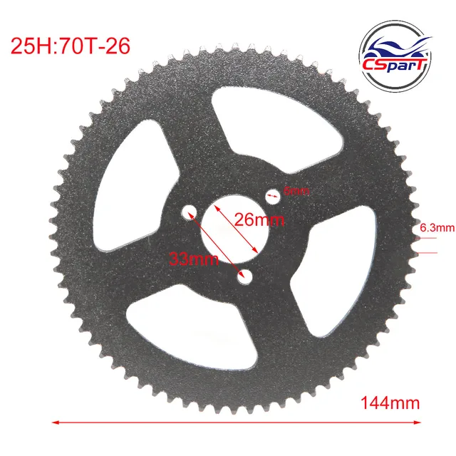
But I will try to search for 3D models/STL sprockets with the same ratio because I believe I will have to increase the thickness of the sprocket and the chain.
I could only find this 3D model on GrabCad with a sprocket with 70 teeth and this one for the 7 tooth (I can't believe this was the only links I found with 7 and 70 teeth, bruh).
Of course, I will have to check if the space between the teeth is compatible and probably modify these.
I will first to find a more robust sprocket chain first, the one I showed in the previous project log wasn't that good for this application, since the chain connections where push-in connections. Which wouldn't last much on a system such as this.
Well, I found this chain for motorcycles on the GrabCad website, and it seems like one of its chains can even be 2D cut on any medium (or this one).

3D modelling:
Anyway, putting it together on Blender:

I took a teeth from the original sprocket (on the left) and used an array modifier to make the teeth both in the 7 toothed sprocket and the 70 toothed sprocket.
However... There is a little problem: the original sprocket doesn't have 70 tooths, it has 69 (nice).
It is not a big deal tho, I will have a little broken ratio of 9.8571, but it is almost 10:1.
Well, I felt like I did an half-assed attempt on making a sprocket gear, so I decided finally look for a tutorial on how to make sprockets on FreeCAD.
(and yes, this "I didn't try hard enough" is one of the reasons that I simply never finish this stupid project)
This is me 5 hours later, I couldn't understand heads of the program and no matter how much I looked, I couldn't find any kind of image that fitted in the specifications of the chain.
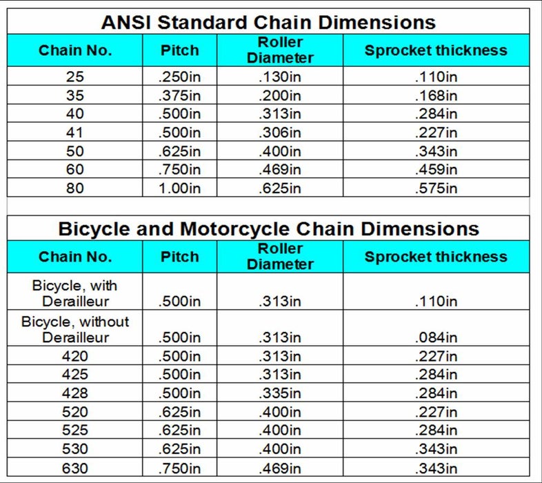
No matter how f#$king much I tried, it simply doesn't appear on google and I can't understand a hint about the tutorials...
Well, guess what? The sprocket, chain and the other links I posted here don't match up no matter how much you change them.
So this means that I will have to make my own sprocket from the ground up anyway.
The best I can do is copy the scale of a real chain and built a sprocket from the spaces between said chain.
I thought first on editing the chain itself from the links I posted, but I just say this wacky chain that I think it will be easier to make on blender:
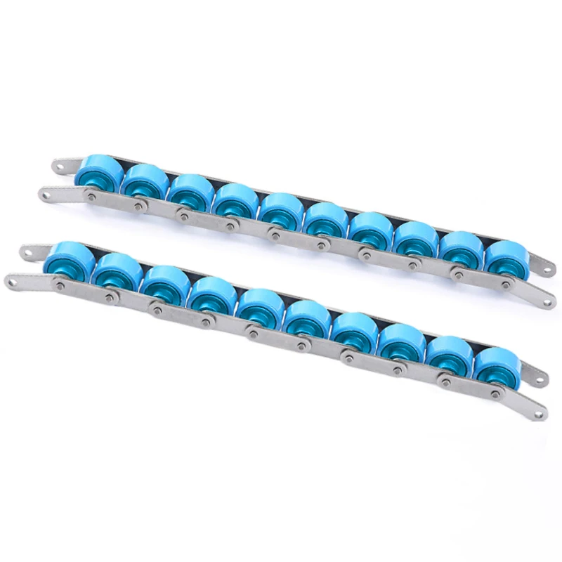
Dunno what will get out of this, but these circles seems way easier to make and put together...
The only problem is that, unfortunately, I will have to make almost every part from the ground up.
I wish I could just put together a list of off-the-shelf parts on this thing, but unfortunately, the more I search for off-the-shelf parts, the harder it is to find parts online.
Not to mention that sometimes, these parts are really expensive.
Yeah, one or two would be fine for anyone to buy, but you would need dozens of these.

By the way, the reason I am so invested on sprockets instead of gears is because of the resilience and efficiency of sprockets.
The sprockets distribute the loads more efficiently, not to mention that I was planning on actually make it without the laser cutting, because since the sprocket will depend on the diameter of the chain rollers. So you can actually make one by hand without much trouble (I think).
But at this point, screw it, let's go with gears...
I found these gears on thingiverse that go from 10 to 120 options.

The big gear has 15cm in diameter, the smaller one has 1.7cm of diameter and both have 3cm of thickness.
Obviously, I don't intend on using the entire gear like the way it is, I will put holes on it to aliviate the amount of material required, and even cut it in half depending where it will go.
Also...
I could just have done this from the start... I think...
An actual engineer (like James Bruton) would have finished this stupid project long ago.
Right now it has been 6 months since I started this senseless endeavour.
Everything I do in this project feels like a infinite roadway where my knees are being dragged into the asphalt.
... But we have to keep going anyway xD
So, back to the subject:
So, just putting a single gear wouldn't be a wise decision (accordingly to my gut feeling), because too much load would be being applied to a single gear teeth made out of plastic.
So, the idea is to put 1:1 gears around the bigger gear.
Well, I do think it would be better to distribute the rotation/torque to each gear with a sprocket, but I'm way past that... >.>

Something like this, but I was thinking in a gear transmission without looking like a dumb pyramid...
Also, I did thought on using less powerful electric motors for this... But it would get more expensive than just buying a single expensive electric motor (as far as I was able to find).
Also, I just found this video, where the guy explicitely makes this actuator to be laser-cutted, while the james bruton one was made to be 3D printed.
Although I don't know how to change it yet, I'm waiting the guy to post his files.
Of course, I won't just wait still waiting the guy to release it, I will try to modify James bruton's cycloidal drive in order to be "laser cuttable".
Just to remember: I have a 3D printer and I hate that piece of garbage, and thus, I'm choosing laser cutting for its precision and simplicity.
Another day were this project didn't magically finished itself...

Well, I tried to make a "mockup" of the final thing with what I got so far, and...

That sure is an ugly looking exoskeleton...
These big gears/sprockets really don't seem strong enough for the job... I believe I will have to find another kind of power transmission or simply making the actuator stronger...
Yeah, I guess I will have to use a winch mechanism, one with 1.5cm of diameter with a rope connecting both sides of the limb.
... And all of this trouble just to go back to that...

Funnily enough, while I was looking for winch mechanisms, I came across this interesting piece of winch mechanism, that actually is a linear actuator:
Other relevant subjects to the project (Off-topic?):
Also, I was wondering how to make a DIY efficient Hydrogen Fuel Cell.
I heard these are expensive because they use platinum coated/pleated catalysts...
But if I go to google shopping, platinum coated/pleated metal wires are quite cheap, strangely enough.
I just don't know how those things are made... 🤔
I asked around and I found this answer:
"Wire is platinum plated; fuel cell elements are coated, which is many times thicker; the amount of platinum plated onto an entire reel of wire might be as much material as would wet your finger if you lick it; in a fuel cell, you might find ounces of the stuff."
... Well... It makes sense now...
Well, I wasn't quite satisfied, so i searched a little more:
So I decided to look at how exactly hydrogen fuel cells are made.
And it looks like it is relatively easy to make and build, the most expensive parts are the catalyst and the proton exchange membrane (that I think you can use from normal batteries).
The catalyst anodes are basically porous graphite with platinum nanoparticles, basically an sponge.
I was thinking on buying platinum pleated wire to a fine powder (or just roll it inside a graphite sponge) and stacking it up.
I searched a little bit, and a 50kw fuel cell for cars uses around 20 grams of platinum.
Welp, I need 10 times than this, so I would gess that 2 grams of platinum are enough.
Of course, I feel like it is not that simple and there are a lot of crap necessary for a good and efficient fuel cell...
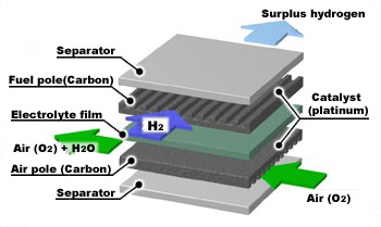
Welp, it seems like both the anode and cathode are porous graphite with platinum nano particles...
I did find out that there are other types of hydrogen fuel cells that are more efficient and don't need rare minerals such as platinum.
One of these is Molten Carbonate Fuel Cell, these normally are for industrial use and are quite complex to build.
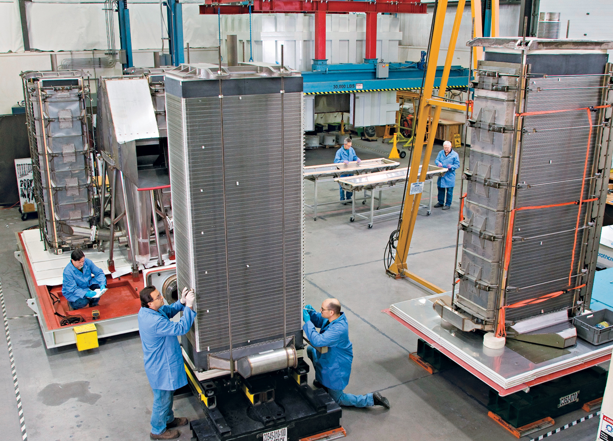
Anyway, this one is a Molten Carbonate Fuel Cell for a 1 megawatt (1 million watts) power plant.
Also, I found a generator that is really light and can deliver 4kw of power (5.3 horsepower) and isn't obscenely expensive.
It is called "Digital TG4000I Toyama" or something like that.
It weights 30 kg with fuel and all.
Even if I had two of these stacked, it would still weight only 60kg while delivering 8000 watts of power.
Generators with this kind of output weight around 100kg or double of that.
I still didn't calculate the final output, but hey, at least I have to get some good news, right?
Also, this guy made graphene in the cheap, I wonder if it can be of any use in this project...
I tried to search for graphene hydrogen fuel cells, but there simply isn't much concrete conclusions on that.
It is always the "graphene can make fuel cells more efficient", saying "can make" doesn't mean these "will make".
I always heard that graphene and carbon nanotubes "would change batteries forever and we wouldn't need lithium anymore".
Guess what? We still need lithium, the batteries only use graphene to protect the anodes and cathodes from deteriorating, nothing that exciting... :/
This and the other video about graphene that can be made at home, makes me wonder: should I go back to hydraulic power?
UHMWPE composite that I talked about on Project Log 45, with this graphene, could make things quite interesting...
For a moment I thought that I could make the hydraulic cylinders and the hydraulic pumps out of UHMWPE composite with graphene... But the problem still is the power transmission efficiency...
Also, I totally forgor that hydraulic systems tend to heat up a lot during compression...
So, anyway, in my frustration (as written in this Project Log) I was researching for more efficient artificial muscles and I finally found the efficiency of carbon nanotubes and graphene.
... It is 0.5% of efficiency. :|
I asked on quora and its version of ChatGPT, the "poe" answered the following:
"I'm not aware of any artificial muscle or soft actuator that can achieve the same efficiency as electric motors across the board, but there are certainly some promising developments that are worth exploring.
Silicone-based soft actuators, such as those made from SilicONGEL, have shown some potential in terms of their efficiency and performance. SilicONGEL is a type of polymer that can be engineered to have specific mechanical properties, including high elasticity and the ability to generate significant force when subjected to an electric field. This makes it well-suited for use in soft actuators that can mimic the movement and function of natural muscles.
While the efficiency of SilicONGEL-based actuators may not be as high as that of electric motors across the board, they can still be quite efficient for certain applications. For example, researchers at the University of California, Los Angeles (UCLA) have developed a SilicONGEL-based actuator that can generate a specific force of up to 1.2 newtons per gram while consuming only 0.7 watts per gram. This translates to an efficiency of around 42%, which is quite good for a soft actuator.
Overall, while there may not yet be an artificial muscle or soft actuator that can match the efficiency of electric motors across the board, there are certainly some promising developments in the field that are worth exploring further."
"A processable, high-performance dielectric elastomer and multilayering process"
It is "just" 42% efficient, but I don't know how much it costs, how hard it is to make and how well it works. Even so... At this point, taking into consideration how much it weights and how much the current exoskeleton would weight... I don't think that's much problem, to be honest.
Assuming it is relatively easy to make, of course...
I requested to view to article on ResearchGate, so I hope they give me permission to read it...
The only place I found some informations of the material was this website.
So... Assuming it is "just" acrylic with silicone and some conductive material, then it would be cheaper to make than buy a 300 reais electric motor for each joint...
Not to mention that I could have the option of making an "augmentation" exosuit, which instead of giving the user super human strength (like lifting 100kg+ for X hours), it would only give the user a support and help on areas with more tendency to be hurt.
Such as the knees, the feet and the back.
It could even be useful for the eldery that have difficulty walking and so on.
I just crossed upon this video about ignition coils for car engines.
Why is this relevant to artificial muscles?
Welp... Dielectric Elastomers use very little amperage, but large voltages, because essentially, they are working with the electric static.
A 10,000 voltage supply with 0.0001 amperage is still 1 watts of power.
Unlike normal transformers, the ignition coil drivers get full charge in miliseconds and reach 10,000 volts when the energy supply is suddenly cut.
This could mean that instead of relying of incredibly heavy and dangerous power conversion systems, a dielectric elastomer system could work with pulses instead of keeping the energy always turned on.
I don't know if this would make much difference, but in my smooth brain, I thought it could make the system more efficient...
... Besides, maybe one could make flash graphene using one of these instead...
This video shows a leg mechanism that I thought it was kinda interesting, but I don't know if I should even try something similar:
Also, I'm starting to doubt the results of my little experiment with 30 rpm movement of the human body...
I was looking at this rpm visualizer and this article on research gate.
30 rpm seems too dang slow, and on the article is said that the people achieve 180 rpm average. Although I don't know if it is 180 rpm on each joint or on the treadmill.
However, ChatGPT said the following:
Me: How much rpm does atlas robot achieve?
ChatGPT: As of my knowledge cutoff in September 2021, the Boston Dynamics Atlas robot had a maximum joint speed of approximately 15 revolutions per minute (rpm). However, please note that my information might be outdated, and there may have been updates or improvements to the robot since then. I recommend checking the official Boston Dynamics website or contacting them directly for the most up-to-date information on the capabilities of the Atlas robot.
On the own Boston Dynamics website, it is said that the atlas robot can achieve a running speed of 2.5 meters per second, which is around 9-10 kilometers per hour.
Assuming that the exosuit will move at twice the 15 rpm speed, then it would achieve around 20 km/h.
On the google, it is said that the average human speed is around 10 km per hour, very close to Atlas.
I know it is annoying for me to always bring up the same subject time and time again, but taking into consideration the amount of mistakes that I've made throughout this project, I think it is necessary to always check constantly.
_____________________________________________________________________
Discussions
Become a Hackaday.io Member
Create an account to leave a comment. Already have an account? Log In.
"I have a 3D printer and I hate that piece of garbage"
Does it have a bowden tube extruder? If so, convert it to direct extrusion. That made all the difference on my CR-10. Also make sure the frame is square and all axes are perpendicular. I used aluminum foil as shims to adjust mine.
3D printers are never super precise, but still a very useful tool to have.
Are you sure? yes | no
It is a Ender 3 Pro, but basically, it is just like owning a regular printer, no matter what you do, there will always be an error or an annoying defect that appears.
Are you sure? yes | no
Looks like that is direct extruder already, so should be similar to my modified CR-10. I wonder what the problem is.
Are you sure? yes | no
I'm also wondering what the problem could be. The way you described it made me think you had some old Anet A8 or Tevo Tarantula. I wonder if printing at 30mm/s and/or a 0.2mm airbrush nozzle for higher print quality would assist. It's slow, but as long as it's reliable, it'll be faster than "next day delivery" from an online store.
Are you sure? yes | no
Well, I can't answer replies to a comment, only add new ones, but I will try to explain with an example:
I wanted a cellphone holder for my desk, then I took my time to level the bed as precise as possible, with those squares and curves, so I would have certainty that nothing was wrong (it took me 1 entire day).
Then I took my somewhat expensive 1kg filament, added to the printer and tried to print a cellphone holder for my table.
I put the highest and slowest quality with the ideal infill and so on.
And guess what? EVERY print I did had something going wrong, the print warped absurdely (even though I have the 3d printer inside a case), some times the final print simply broke on my hand or the print simply became a ball of useless molten filament.
I changed the settings, the filament, the extrusion nozzle, the bearings, the gears, loosened/tightened the screws, changed the STL file to other options and nothing worked.
I tried to make benchy boat, it went fine, then tried other calibration methods, those also worked, redone, done, repeat and so on.
Everything worked, *except* the damn cellphone holder.
I wasted weeks of electricity, time and filament to print a cellphone holder that costs less than 10 bucks on the internet. :|
When it comes to 3D printing, I'm almost ascending on frustration alone.
Are you sure? yes | no
Oh yeah, having the printer inside an enclosure is important. I had a lot of trouble with warping before I did that, because the hot air rising off the heat bed would pull in cold air from the sides and cool the plastic too much.
Is your filament PLA or PETG or something else? I use PLA for everything unless I have good reason not to. I always have trouble with bed adhesion and layer adhesion with PETG. Although I read recently that you're not supposed to use the part cooling fan with it so I need to try that next time.
If other models printed ok, then there's probably something about that particular one that needs adjusted to make it more printer-friendly. Although a cellphone holder seems simple enough that I'm not sure what would be wrong with it.
Are you sure? yes | no
I also use PLA.
... Yeah, I also don't know what is wrong, but yeah... I hate 3D printers now. lol
Are you sure? yes | no
That "I just need to finish this project" is me for at least 10 project simultaneously.
Are you sure? yes | no
🫂 dang bro
Are you sure? yes | no
lol, same. My greater robotic bird wing project has a zillion sub-projects that all need attention. But I also want to work on an outrunner version of rq3's fancy 3D printer extruder https://reprap.org/forum/read.php?424,888537
And yet what I've actually been working on is guitar string tuners using strain wave gears (tiny things, machined with 0.5mm end mill). Which is totally unnecessary, but great fun.
Are you sure? yes | no