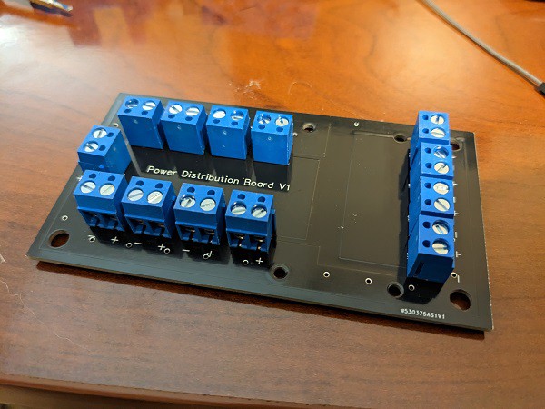
So the last power distribution board I made was a bit of a mess to say the least... It worked, but I really wanted to make a proper PCB. That way, it wouldn't look so janky, I could getter better current flow, nice mounting holes, and get a place to put the voltage regulator.
That's where PCBway came in. I'm guessing the rep saw the previous board and decided I needed some help :)
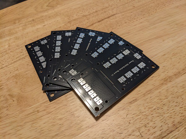
Any ways, I used easyEDA to draw up a schematic and board, sent it to PCBway and a week later these bad boys appeared in real life! I'm super pleased with the quality of the boards and the turn time on the order.


A couple main things I was trying to achieve in the design:
- large pathways for current to flow (I have asperations of using this on some larger builds in the future)
- I did this with polygon pours on the board
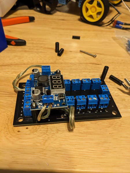
- spot to mount voltage regulator and have it's voltage distributed separately
- I didn't think about the full size of the VR on this and needed to give it some more space. Thankfully I have a 3d printer and made some standoffs
- pads to solder wires directly to instead of using the screw terminals
- I thought I was being clever by making them use the same pads as the screw terminals, but it was kind of a pain to solder to, I'll make them separate in the next iteration

 David
David
Discussions
Become a Hackaday.io Member
Create an account to leave a comment. Already have an account? Log In.