So, after a good bit of time, I was able to put together 3 of the main parts of this project. This should really get this thing going. It took a good bit of searching, recoding and trial/error got it working. So I'm pleased with that.
I did a push to GitHub for this bit of code. This is mainly for motor control and stabilization. The code can be found here. If anyone wants to have a look at it. Suggestions and help are more then welcome.
PWM
Okay, so jumping into what has been done. First, started off with getting the PWM working correctly. This was accomplished using LEDC from ESP-IDF. This can all be found in the component directory of your ESP-IDF installation under C:\Espressif\frameworks\esp-idf-v4.4.2\components\driver\include\driver\ledc.h dependent on your install of course. At first I tried to find an exact replacement that Arduino was using for the build environment then decided to just cut out the middle man and go to the source it's self. There is a good example of how this works, which I went off of here. Props to the author for keeping it simple and to the point. Gave me a good spot to jump off of to start searching/digging from there.
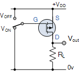
At this point I had to flush out the hardware design for the DC motors. Since the MOSFETs I would be using are P-Channel Enhancement mode MOSFETs both the gate and source had to be tied to Vcc and the drain tied to ground.

The gate was tied to Vcc via a pull up resistor to keep the MOSFET in the off position. What I did here was just create an electronic switch. Were the logic from the GPIO pin is set to Pulse Width Modulation will toggle this switch to give the desired power to drive the DC motor. For my usage, the logic of the GPIO had to be inverted to compensate for this reverse logic setup of the MOSFET.
If you'd like to learn more about basic electronics check out this site and read up on some of the basics. There are allot of good sites to check out, just pick one that feels good for you and charlie mike. I used a bunch of different sites while I was attending school so no site is a one size fits all, that I know of yet.
PID and MPU
After all that was said and done, got a solid test out of my setup, I went on to the next piece. Tying the MPU, PID and PWM together. I did find a software PID library that was used in the Arduino code I had used already in the Arduino build environment, it just needed a little bit of a modification to get it to work with the ESP-IDF build environment. The Original code can be found here if you want to play around with it a bit, the modified version is included in the component directory of my Git repo for this project.
PID can be a pretty big subject and used for more than the application that this project is using it for. So if you want to dive deeper into this area you can check this out and read up on the subject. As I'm just going to touch on a few things here to show how I'm interacting with the PID controller.
As a basic jest of it. I'm getting the yaw, pitch and roll from the MPU converting that number to an angle then feeding that number into the PID control via an input. But first the PID controller needs to settle for a little bit. the setup I got going it doesn't have any PID tunning, if left for brief period of time the controller will level out giving a better result. the following code achieves this to an extent.
// PID Cal while throttle is at 0
if (target_speed[0] == 0)
{
    ESP_LOGI("PID", "CALIBRATING...");
    ypr_cal[0] = ypr[0] * 180 / M_PI;
    ypr_cal[1] = ypr[1] * 180 / M_PI;
    ypr_cal[2] = ypr[2] * 180 / M_PI;
}
I know this is a sloppy way of doing but it'll work for now. what really matters is the input variable being set here, from the data we got from the MPU.
// getting yaw, pitch and roll from MPU
mpu.dmpGetYawPitchRoll(ypr, &q, &gravity);
printf("YAW: %3.1f, ", ypr[0] * 180 / M_PI);
printf("PITCH: %3.1f, ", ypr[1] * 180 / M_PI);
printf("ROLL: %3.1f\n", ypr[2] * 180 / M_PI);

// setting the input for the PID functions
roll_input = ypr[2] * 180 / M_PI - ypr_cal[2];
pitch_input = ypr[1] * 180 / M_PI - ypr_cal[1];
yaw_input = ypr[1] * 180 / M_PI - ypr_cal[1];
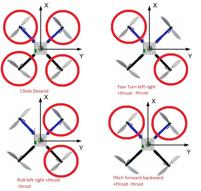
Now with the input set for the PID we can use it's output to adjust the control of the motors with the following.
void motor_control_stabilization (int* curr_speed, int* act_speed, double roll_diff, double pitch_diff, double yaw_diff)
{
    /*
     *   As roll_diff goes positive it will roll left as roll_diff goes
         *   negative it rolls right. This goes for all outputs roll, pitch
         *   and yaw.
     */
    act_speed[0] = (int) curr_speed[0] - (roll_diff) + (pitch_diff) - (yaw_diff);     // FL
    act_speed[1] = (int) curr_speed[1] + (roll_diff) + (pitch_diff) + (yaw_diff);    // FR
    act_speed[2] = (int) curr_speed[2] - (roll_diff) - (pitch_diff) + (yaw_diff);    // BL
    act_speed[3] = (int) curr_speed[3] + (roll_diff) - (pitch_diff) - (yaw_diff);    // BR

    for (int i = 0; i < 4; i ++)
    {
        if (act_speed[i] < 0 )
            act_speed[i] = 0;
    }
}
This can be demonstrated better with an illustration.

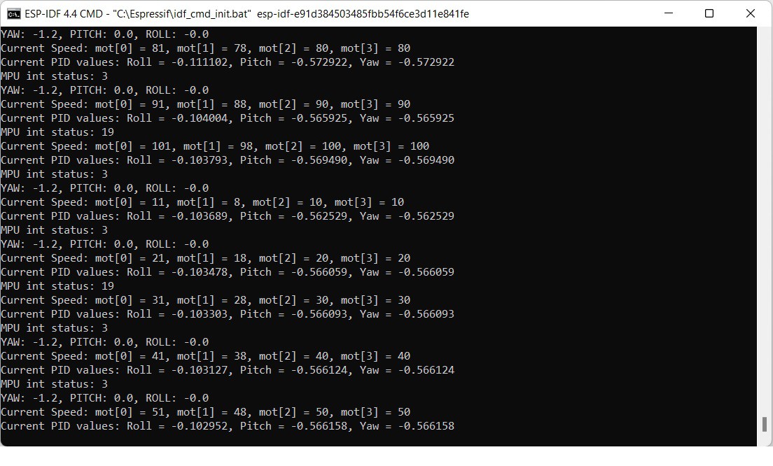
With the code and hardware sorted out, gave it a shot and flashed the firmware to the ESP. The output looked good to me sitting stationary on my work bench.

With that, I'll wrap this up, still got a bit more to do. Need to add the camera and communication code to this project and it'll be near completion along with a test flight and maybe some video to follow. Along with some build instructions.
*sorry for the write up earlier need to proof read these before I post them.
 Jon VB
Discussions
Become a Hackaday.io Member
Create an account to leave a comment. Already have an account? Log In.