Principle of operations
Like the V1 board a PPM frame is generated by the MCU.
I have choosen an ESP32 board for that (more modern than the old PIC18F4550).
As this MCU does not have an USB interface, I have connected it to a mini USB host shield based on the MAX3421 chip
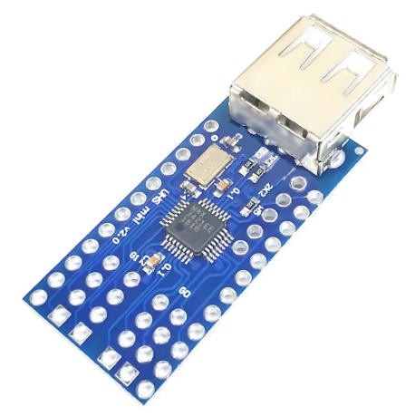
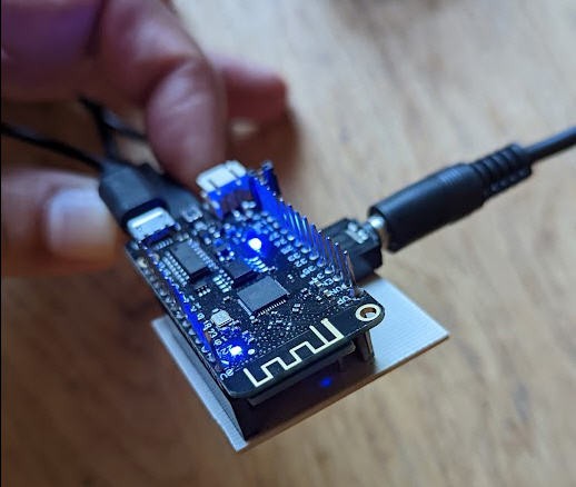
The ESP32 lolin Lite board is mounted in "Mezzanine" above this shield, the result is a quite compact device that can be powered by a USB powerbank.
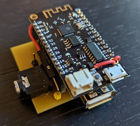
It has a USB A female port to connect the joystick and a Jack female port to connect to the radio's trainer port.
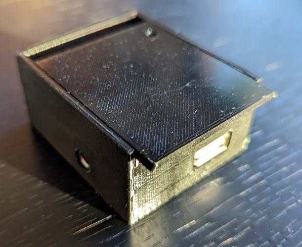
All this can be hidden into a 3D printed case which is available on Thingiverse.
Configuring the board
As this new setup works without Android App, I had to find a way to introduce a kind of Man Machine Interface to configure the board.
I have simply used the ESP32 WifiManager library capabilities to do this.
So if you boot the board (or reset it with the reset button) while touching the small pin close to the jack connector, then the ESP32 exposes a Wifi hotspot on which you can connect any smartphone (or PC)
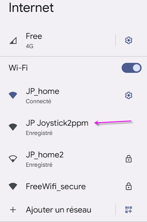
Connecting to it will automatically open a configuration window
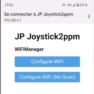
You then have to choose an exisitng wifi network for which you have the credentials, enter them into the form
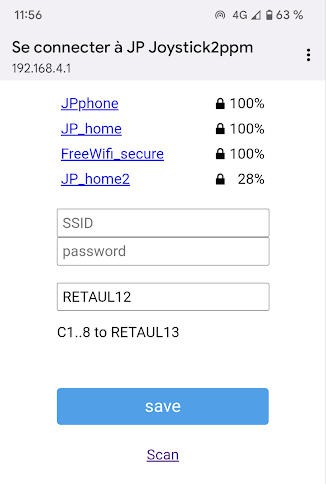
Then you can change the magic sentence "RETAUL13" to configure the 8 channels of your board.
You can affect any stick, any button( 1 to 8) and hat to any channel. The syntax is simple :
REATUL12 meens:
- Channel 1 of PPM will be affected to Rudder
- Channel 2 of PPM will be affected to Elevons
- Channel 3 of PPM will be affected to Throttle
- Channel 4 of PPM will be affected to Ailerons
- Channel 5 of PPM will be affected to Up/down button of the hat stick
- Channel 6 of PPM will be affected to Left/right button of the hat stick
- Channel 7 of PPM will be affected to button 1
- Channel 8 of PPM will be affected to button 3
And that's it, click on save and wifi will disapper while the board reboots and outputs the PPM signal.
So if you want to change this setting you can for intance write : TRAE123L
This will configure this way:
- Ch1 to Throttle
- Ch2 to Rudder
- Ch3 to Ailerons
- Ch4 to Elevons
- Ch5 to button1
- Ch6 to button2
- Ch7 to button3
- Ch8 to Left/right hat
Schematics
Well nothing complex here. Just connect the ESP32 board to the USB Host shield...
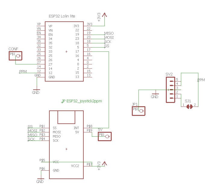
SImply note that the 5V supply for the shield is pick up after the USB plug of the EPS32 board. (red wire on the photo). SO a single USB power bank will power both the ESP32 and the USB shield.
PCB
A quite simple PCB has been home made.
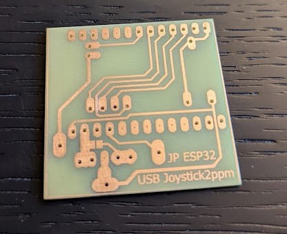
leading to a very compact form factor
You can download the eagle files here
 JP Gleyzes
Discussions
Become a Hackaday.io Member
Create an account to leave a comment. Already have an account? Log In.
I've been looking for just this thing for some time! I hope you will publish the code soon. Hopefully with lots of commentary so it can be adapted to other boards. I would think one of the micro controllers from Ada fruit that is open to being programmed in Python would be great for future proofing the code.
Are you sure? yes | no
i am very interesting in this project can it use with difirent hotas ?
Are you sure? yes | no
Hello. I search the internet, but i cant find the code for this project. Am i so stupid or is there no code here? i would try this project , so my daughter can fly my plane, eventually.
Are you sure? yes | no
Hi,
You are right the code for this particular board hasn't yet been published.
Are you sure? yes | no