-
Wonky unlabelled CGA, jumpers located?
08/24/2019 at 04:08 • 0 commentslong story short [I'm certain I rambled about it quite a bit, here, in the past]...
The CGA card didn't sync via composite with my TV [and not at all with an LCD-TV, showing literally nothing]... ultimately I wound-up switching unlabelled jumpers iteratively, and after 8 of 32 possible combinations, managed to find a setting that worked-ish. I stopped there, as I had other goals...
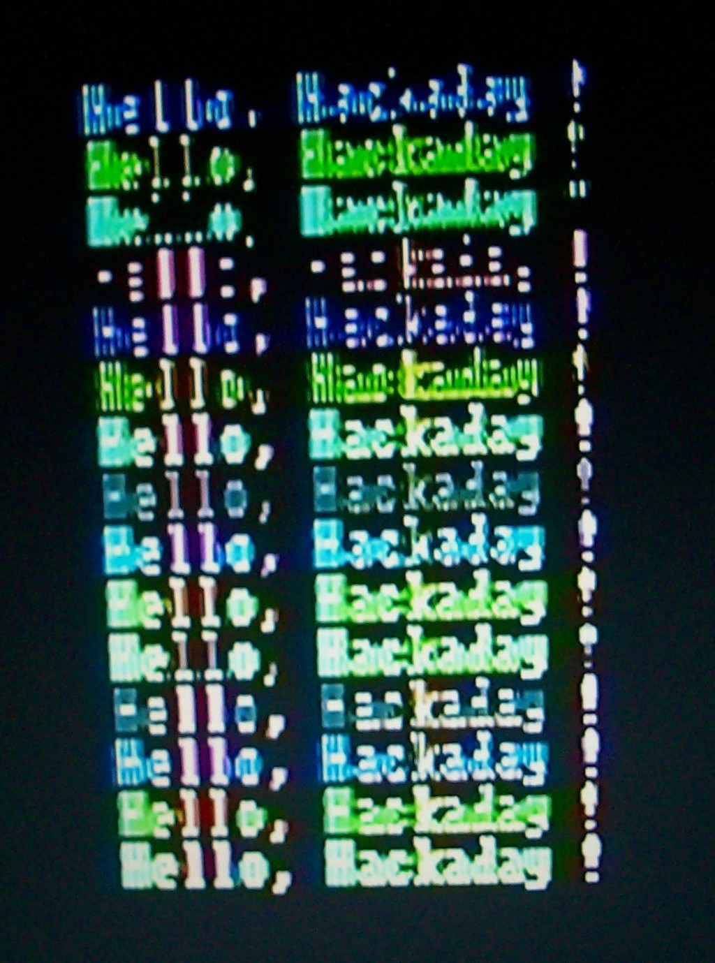
Later experiments turned-out pretty funky, graphically... [look through that gallery! It's kinda groovy, really...]
[This was supposed to be a screen full of red 'A's on a white background. *some* of the wonkiness had to do with improperly timing the ISA bus via an AVR, e.g. the white-on-black portions, but the card itself is responsible for drawing the characters, and those red rows certainly aren't any character I'm familiar with.
Further syncing-wonkiness is better seen below, where I used the normal 8088 configuration and regular ol' BIOS calls to cycle through the colors. Note that red is completely illegible.]
But it was good-nough for the experiments i'd wanted to run [eventually, and quite a bit, running off the AVR].
Recently I remembered a great resource for figuring out jumper settings on unlabeled ISA [etc.] cards... and even though this project's been in storage for some time, I thought I'd see if I could find the proper jumper settings.
BTW, that resource is called "Total Hardware 1999," apparently originally from a company called MicroHouse, and seems to have quite a story behind it, which is why I won't link it here... but look er up. It's *amazingly* handy for old unlabeled hardware.
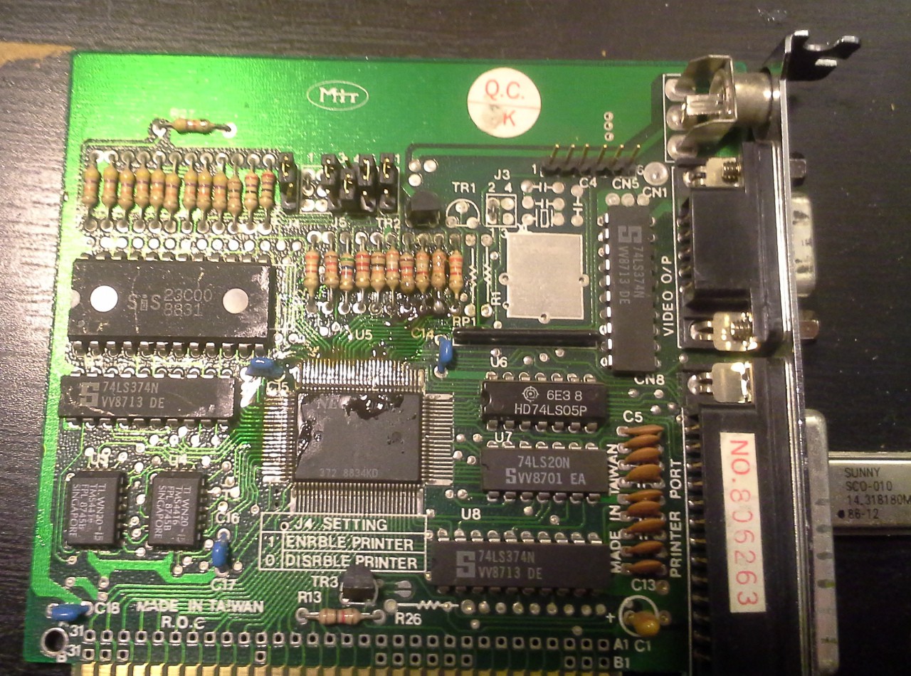
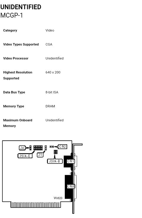
The key, here, is that my CGA card barely has anything as far as identifying/informative markings.... [image from a previous post].
![]()
Look Ma! I can turn the printer port off-n-on! And... that's it. Oh, I know enough about these to identify the Light-Pen connector, too.
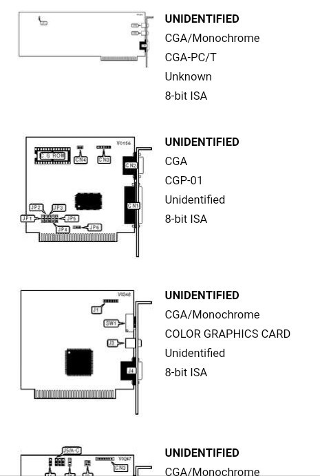
So, TH99 has a browsable page full of great art showing boards as line-drawings with identifying features clearly visible.
![]()
Click the image, find the jumper settings!
[Screenshot taken from a company clearly making money off of someone else's hard work, and not even giving as much credit as to just list the name of the original document! BTW, I will not link them, here, either.]
I browsed first by looking at the backplate; surely CGA cards with composite and parallel ports were common...?! Well, only one with a similar configuration, and it happened to be EGA.
Actually, I'm not surprised, the ports are jammed together so tightly, I ultimately wound-up soldering a header and external composite connector.
But, not finding my card in TH99 was kinda disheartening, until I had an idea..
Surely many CGA cards had similar features... at least I could get an idea of what the jumpers *might* do by looking at settings on other cards...
So I opened up new tabs for several cards which had a similar number of jumpers...
And, learned about some settings my card's jumpers *might* configure, like 5x7 vs. 7x7 fonts, or LPT port base-address...
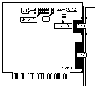
And then I stumbled on thus one...
![]()
![]()
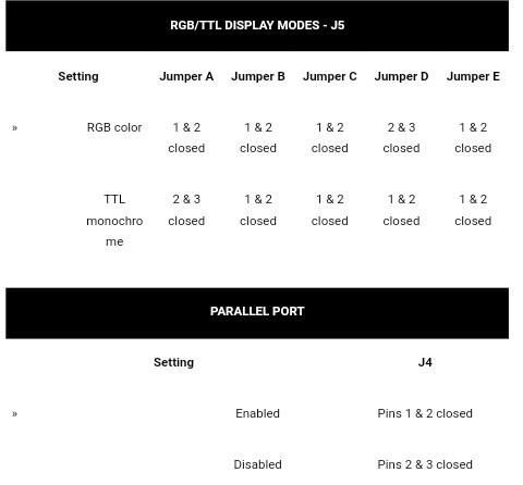
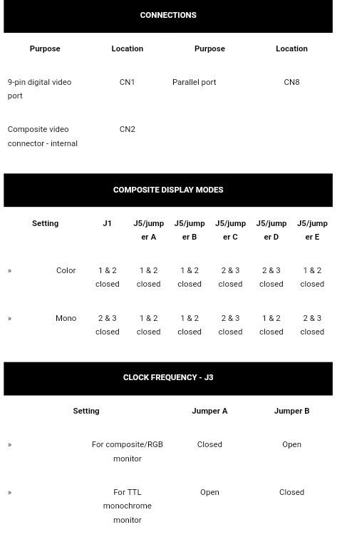
Note my card's connectors and jumpers match in name almost exactly. J5 is labelled 1-5 on mine, rather'n A-E, but otherwise we have what looks to be a darn-near perfect-matching "spinoff," with a couple extra features [RCA and light-pen connectors] and a couple missing/bypassed [jumpers soldered for color mode only, B/W timing circuitry removed].
Further investigation shows the jumper-settings I came up with aren't spec'd... a weird mix of RGB-TTL monitor settings but set to composite output, which might explain the funkiness.
![]()
![]()
![]()
...so... let that be a lesson to ye... when trying to identify a board visually, keep in mind there may be some things missing or extra, maybe, I guess.
[Note, this post mostly for myself, whenever I get to digging this from storage]
-
Believe it or not...
11/27/2018 at 05:58 • 0 commentsI have an idea involving #Incandescent RAM and this project...
-
"Microcode"
11/27/2018 at 05:19 • 0 commentsTurns out, it would seem, that what I've off-n-on approached doing, here--in "emulating" the x86 instruction-set on a RISC architecture--is pretty much *exactly* what Intel did in switching from P5->P6, and beyond...
No kidding! Apparently x86s, since then, are RISC processors with "microcode" to process CISC instructions.
So, those instruction-handlers I started visualizing early in this project aren't attempting to "emulate" the x86 architecture any more than Intel's own x86 processors emulate x86 processors.
MICROCODE!
-
Blogged!
05/25/2017 at 07:07 • 0 commentsMuch Thanks to Jenny List for an excellent write-up about this project!
Not quite as cool as a jet-engine on a car, but I'm pretty proud of this ;)
Who knows, maybe I'll get back to it soon!
-
The Beginning...ish.
03/31/2017 at 06:59 • 2 commentsMoved here from my project-ideas page... *long* after having-begun.
Processor Replacement... (2-4-16) (and some new thoughts 2-5-16)
What about placing a microcontroller on an old motherboard's CPU socket...?
Kinda digging this idea, but haven't really thought it out too much, yet.
AVR would be difficult-ish, since code can only run from FLASH. (Though, have seen some impressive work on that front, running 'code' externally from SRAM, SD-Card, etc. via function-calls...?)
PIC32... well, there's already linux's for that, right? So plug a MIPS core onto an old 486 board, get some ISA slots, PCI, whatnot... Maybe even SDRAM... And plausibly be able to use the already-available linux drivers for those cards...
Not sure how much effort this would take... might need some nitty-gritty details on the bridge-chip(s), OTOH, e.g. 486-era bridges were pretty durn simple and pretty standardized... right?
So, obviously, the BIOS won't be executed (though, I suppose, execution of the BIOS could be emulated), but since it'd be a microcontroller, it could have its own BIOS in firmware...
Not sure why exactly this seems like a cool idea to me...
Some thoughts...
Per my recent experiments with 486 chips, in #Random Ridiculosities and Experiments, it would seem the 486-era was the transition from 5V logic to 3.3V and below... 486DX4's, for instance, have 3.3V core logic, with 5V tolerant I/O, whereas the 486SX is 5V-only... The DX4 was, it would seem, designed to be placed in an SX's socket as an upgrade. (Or, plausibly more important, designed to be used with industry-standard design-practices at the time, which just happen to be somewhat compatible with most hobbiests' abilities). Thus, a 486 mobo being a reasonable starting-point for such an endeavor. I haven't looked into Pentiums and beyond, but I'm guessing as of the later processors, there's probably some likelihood that their interfaces may be 3.3V or even lower. This might lend itself well to e.g. a PIC32 replacement, BUT (again, I haven't looked into them), it's also quite plausible that later processors use a less-standard I/O scheme, being that they may *rely* on the fact of bridge-chips. E.G. newer processors may use 1.8V, or LVDS, or who knows what... It's plausible they don't even use an Address/Data I/O scheme at all, in favor of some sort of newer "transport" scheme made specifically to work with bridge-chips. I really don't know. All I know is that I was pleasantly-surprised to find that 486's (which I just happened to grab at-random) still supported an I/O interface that makes sense to me...
Oooh, a *QUICK* overview of : http://download.intel.com/design/pentium/datashts/24199710.pdf Suggests that Pentium processors may be quite similar to 486's interface-wise. A BRIEF overview (and an utter lack of knowledge) suggests that the major difference is a 64-bit data-bus, as opposed to 32-bit. OK, that's Doable... The P66 uses 5V signals, the 75-200MHz chips use 3.3V... Might be doable. 64bit, well... I guess a few+ 74574's could latch two 32-bit data-cycles into 64bit. Doable, anyhow.
And, who knows what those bridge chips are capable of... The 486 definitely had 8-bit and 16-bit interface-*modes*, the Pentium likely has a 32-bit *mode* (despite having a 64bit data-width)... Is there a PIC32 with a Parallel Master Port that supports 32-bits...? hmm... And, even if not, is it possible to *send* the lower-bit-width mode (rather'n receive)? By which I mean... (it's been a while, I could be *completely* mistaken), I think the bit-width is determined by the device... Would it be possible to specify somehow that *all* devices are less than or equal to 32bits (or whatever bit-width the selected uC can support)...? Then, maybe, it'd be possible to rely on the "bridge" to break even a 64-bit device into 8, 16, or 32 bit transactions for our processor... and avoid the necessity for latches altogether......?
Ridonculous? Probably.
Here's a cool one: Someone plugged an ARM into a Commodore 64's CPU socket:http://hackaday.com/2016/07/02/the-dual-core-arm-powered-commodore-64/
And this dude Booted Linux on an AVR emulating an ARM:
http://dmitry.gr/index.php?r=05.Projects&proj=07. Linux on 8bit
-
No More About The KayPro Diskette...
03/03/2017 at 20:52 • 0 comments*This* "project page" is about installing an AVR in the CPU-socket of an 8088-based PC/XT computer.
If you've read the recent logs, you know I've gotten a tad-bit sidetracked on what I thought was going to be a one-night-endeavor and turned into several weeks.
So, now... There's a new "project page" for that, and I'll quit yammering about it *here*.
#Omni4--A KayPro-based Logic Analyzer
(See the next log in that endeavor here:
-------------
Since that guy's occupying so much time/space, it'll probably be a while until I revisit *this* project. But here's a quick overview of where *this* project is at, currently.
I've managed to plop the AVR (ATmega8515) into the CPU socket and interface with components via the '8088-bus'.
Can read/write all 640K of DRAM with nearly 100% reliability.
Can read/write the CGA card (in text-mode), in color, no less. And, after a bit of an ordeal, have managed to get the reads/writes down to near 100% reliability.
(Turns out, I was reading the "READY" (aka "WAIT") signal too early, so the CGA card didn't have time to respond that it wasn't yet ready).
As a side-thing trying to solve the CGA problem, I also can read/write the parallel port.
---------
Future-endeavors, maybe... I've looked into the specs for my SoundBlaster card... and I think I've enough info in there to start producing sound without too much difficulty. Thankfully it can be done without using DMA, because I've little interest in learning to use that blasted thing.
Looks like there are basically two different systems on the sound-card. There's the raw-sample-based system (e.g. for playing/recording WAV files), but there's also a waveform-synthesizer-chip which can be used to generate surprisingly (to me) sophisticated waveforms...
Frankly, my artistry when it comes to graphics/sound is limited... So, I really don't know what I'll *do* with this thing when I get that running. (As is the status with the CGA card which is functional). Maybe some copy of some game... Tetris or something. But don't be expecting any "demoscene"-worthy demos coming from my endeavors.
I suppose I should probably get the keyboard working at some point... Though I could probably more-easily use the RS-232 port.
----------
For now, back to backing-up that blasted floppy-disk.
-
"The Trick" analyzed...
03/02/2017 at 16:21 • 0 commentsUPDATE: A more in-depth analysis of another sector-transition:
![]()
More analysis at the bottom...
--------------------------
Using "the trick" described two logs ago, and the last log's theories of why it's not oft-used, I've been analyzing a track-extraction from the floppy-disk...
![]()
(I'll go into the waveforms more, later).
--------------------
Between each data-section there's a bunch of housekeeping-data. But some of that data is (by design) very recognizable.
Immediately after the data-section (and its CRC) appears to be 24 bytes containing the value 0x4e. This allows the disk-controller's clock to resynchronize between/with each sector.
The first two sectors on the track I'm analyzing appear to be synchronized with each other. And, thus, the clock maintained its sync starting with the first sector, and into the second sector. I can view data starting at 0x0000, and if I count 512 bytes (or just search for address 0x1ff), I can see that data end, followed by two (CRC) bytes, then followed by the very-recognizable 24 copies of 0x4e.
If I continue from there, I can determine some low-level details of the format of the floppy. This one's definitely different than an IBM-PC format (as I've read). One example is that the IBM-PC format uses *80* bytes of 0x4e, rather than 24. (This makes sense... this disk appears to have 10 sectors/track whereas IBM uses 9... those extra bytes have to fit somewhere... so reduce some of those redundant-bytes...) Similar elsewhere. After those 0x4e's is 8 bytes containing 0x00. IBM uses 12 bytes, but, these changes in "gap" size are basically the only major difference.
So, it's easy to see where the sector-header starts (immediately after the 0x00's), and so-on. Thus, I've determined there's 595 bytes used for each sector. 512 for data, and the remaining for sector-headers, CRCs, gaps, etc.
So, if I advance through the file to address 595=0x253, or thereabouts, I actually see the end of the first sector, and into the next sector, and see that the data and header-stuff is aligned just as I expect.
From there I advance to address 595*2... but this time it looks different. Instead of 24 bytes containing 0x4e, I get 23 bytes containing 0x21.
As described, in the previous log, that kinda makes sense... Those gaps are there, largely, for the purpose of allowing the disk-controller to resynchronize its clock with each sector. That way slight timing-variations from one drive to the next won't cause issues like we're seeing in the data-stream here... where 0x4e is coming through as 0x21.
The thought, then, is that what's happening is a slight bit-shift... those 0x4e's are probably written properly to the disk, but since I'm not reading each sector *individually*, and instead reading the entirety of the track as though it's one gigantic sector, the error is due to bit-shift likely caused by the sectors' being written at different times on different drives.
But... 0x21 is nowhere near similar to 0x4e shifted-left or shifted-right by a few bits... so what's happening?
-------------------
MFM. was my theory, and I think I've proven it...
Briefly, storing the data on magnetic media requires both data *and* clock-synchronization information to be stored along with that data. (If you're familiar with SPI or other synchronous serial protocols, this is another way of doing that, on "one wire").
So, MFM is a scheme to assure that the clock stays synchronized despite the fact that one might store twenty bytes containing '0' consecutively. In that case, clock-bits are artificially-inserted... Go check out that link, it served me better than the wikipedia article, and more concise than I could be...
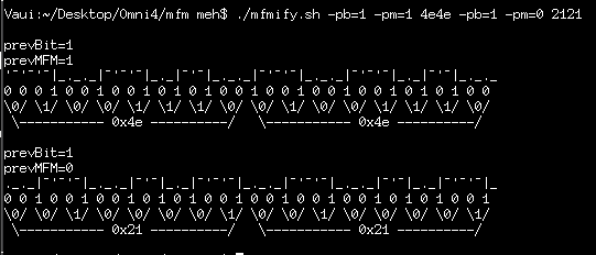
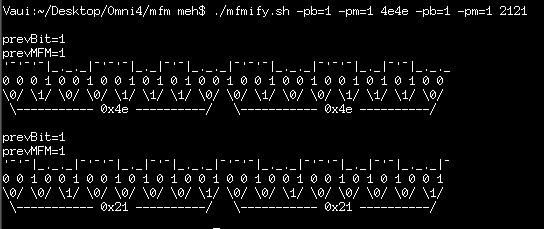
I wrote a shell-script to take in raw byte-data and "draw" the MFM-encoding for comparison-purposes... And, look-here... 0x4e looks darn-near exactly like 0x21, when encoded in MFM, and shifted by *one* MFM-clock.
![]()
So, probably, what happened is that one sector was written at one time... then the second was written... and it just happened to be that the "gap" was used for exactly what it was designed for... The second sector (well, third, in my case) wasn't aligned with the previous, and overwrote its last "gap" bit (e.g. bit 0 of 0x4e) with the new sector's first gap-bit (e.g. bit 7 of 0x4e), and continued from there. Or something like that...
Interestingly, if the previous bit (before the 0x21's were read) was of the opposite level, the value would've changed dramatically.
----------
So, from here, then... I suppose it's a matter of writing a script which can *determine* the properties of the bit-shift on each sector... First I'll probably extract everything into separate 595-byte files. Then something like... I should see those gaps ~20 bytes long with a specific repeating value... Then... well there's a lot to try from there.
The example shown happens to be shifted by a single MFM-bit. Which is half a data-bit. But, the quote in the last log seemed to make it sound like the gap is *so large* because later-written sectors might be *way* misaligned. Maybe as much as 40+ *bytes*. So there's a bit to ponder...
What was the previous bit-value? That might be extractable from the other data in the file... or it may be easier to just guess-and-test.
What was the previous *level* of the MFM-encoding? That can't really be known from the raw data itself... But, knowing what byte we're *looking for* (0x4e) vs which byte we're *getting* will give us enough info to work with... Probably easiest to just guess-and-test, again.
That gives *four* combinations... But then, it could be off by any number of bits and half-bits... so I guess that's 15 more combinations... So, in all, I think there could be 15*4=60 combinations?!
I guess that's what computers are good for.
Handy, then, that there are *so many* gap-bytes, and the pattern of the gaps so recognizable.
-----------
A vague thought that this might be easier if I just didn't treat them as *bytes* at all, but instead shifted through the bits sequentially until it "locks"... but that's a bit beyond me at the moment. (And, again, slightly different than how a disk-controller would do-so, since the controller has the MFM encoding to look at, two bits for every data-bit, and I have only one bit for every data-bit).
This project's ridiculous! I really went into it thinking all I'd have to do is use the "disk copy" command from the menu that it booted into, and that it'd've been done that first night, weeks ago.
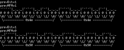
Here's another I'd seen... 0x90's instead of 0x4e's...
![]()
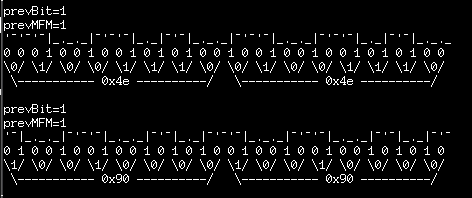
Looks like that, too, is only off by a half-bit. But note it'd've been *entirely* different if prevMFM=1:
![]()
(Then again, prevBit would have no effect on the 0x90 waveform, since it starts with a 1-bit... hmmm)
Ah hah... maybe the levels don't matter at all... I'll have to think about that some more... (note that the MFM encoding stores '1' at a *change-of-level*... hmmm) Well, waveforms are sure more fun to look at.
-------------------------------------
UPDATE:
Here's another case...
![]()
0x7a is supposedly the last CRC-byte of the previous sector. Then there are two bytes which I think should be 0x4e, but instead are 0xfe and 0x82. From there-on, we get 0x12 where the remaining 0x4e's should be.
So it would seem there may be some overlap from multiple sector-writes...(?)
I dunno. Regardless, I'm pretty sure 0xfe and 0x82 aren't supposed to be valid data.
And... it's easy to see here that the "bit-shift" is *way* larger than just a half-bit.
---------
This "project" was supposed to be a one-nighter... it's been several weeks, now... I suppose I should've put this in a new project-page altogether from the start... But I keep thinking it's going to end soon.
-
The Friggin Trick! And why it fails...
03/02/2017 at 05:00 • 0 commentsWhy the method of reading floppy-disk data-tracks, laid out in the past log-entry, is not de-facto...
Again, the normal methods for data-extraction are sector-by-sector. Even the "read track" command technically does-so on a sector-by-sector basis.
(In fact, now that I think about it, I think I could've just as easily used the "read-sector" command, with the trick laid-out in the previous log).
Why *not* extract the entirety of a track, with *all* its data, including CRC, sector-IDs, gaps, and more... and let the PC process it?
Well, here's something:
...the sector is finally terminated by another gap, GAP3, of 80 bytes of 4eh. This gap is designed to be long enough to allow for any variations in recording speed and thus avoid the inadvertent overwriting of the following sector.
That's apparently an extreme oversimplification...
Basically, before every section of information (not going to call it 'data', since that's confusable with the data section, and not going to call those sections 'sectors' similarly...). Between each section of information, be that section the "Sector ID", the "Data", or the "Track ID" sections, there's a "gap" followed by a bunch of "sync" bytes.
In other words, each of these sections of information is kinda like a barcode-label, the read/write head a bit like a barcode-reader. So, on a single track, on a single side of a floppy-disk, containing 10 sectors of user-data, it's somewhat like 21-ish pieces of sticky-backed paper, each with a printed-on bar-code.
They're most-likely *not* perfectly-aligned with each other, nor perfectly-spaced. And most-likely each bar-code scanner (human) will scan each barcode at a different rate, most-likely very different from that it was written-at. Thus, each barcode has its own syncing information. Likewise, each section of information on the diskette has its own syncing information.
So... treating it as "the trick" does... is a bit misleading. In fact, I've just been browsing the hex-dump of a single track and found that by the time the second sector is read, data comes through *completely* wrong.
The sync-bytes are supposed to be 0x00, and yet they appear as 0xff! The gap3 bytes are supposed to be 0x4e, yet they're coming through as 0x21!
(Wait, what?!)
OK, I could expect a certain amount of bit-shift... ... but 0x00 is *nothing* like 0xff, bit-shift-wise, right...? Nor is 0x21 a simple bit-shift away from 0x4e.
So now... I haven't analyzed it *completely*, but my thought, here, is that it's not actually shifted by a whole *bit* worth of data, but by *half* a bit as stored on the magnetic-media... Wherein it's necessary to look into MFM. Essentially, each data-bit on the magnetic-media is stored as *two* "bits" such that each data-bit contains a transition between 0 and 1. (or, maybe, North and South polarization?). The purpose being to allow the disk-controller to *sync* to the inherent "bit-clock" stored in those transitions.
But, of course, since I'm using "the trick" it did that syncing *long* ago, (512 data-bytes, + a bunch of other information/header-bytes), and kept that sync with every bit-transition thereafter, rather than trying to resynchronize with every "sync" section, as it would've if I'd've requested the read of each properly-sized *sector.*
So, for the *first* sector's worth of data everything's aligned properly... The syncing happened on its sector-header. But every "sync" and "gap" section, thereafter, could be *completely* misaligned... maybe a full-bit which would be easy to see, or maybe a half-bit as I think I've found, here... Maybe *several* bits/half-bits... Or, judging by that earlier-quote, it could even be misaligned by *several bytes*.
Further-still... who's to guarantee that each section is aligned at the magnetic-bit-level...? Maybe they're askew by 1/3 or 1/10th of a bit...?
I *think* what'd be seen, then, is a few bytes that don't make sense (after the end of one section and upon entry of the next)... and then after a little while the disk-controller's clock will have re-synced with the edges in the data-bits. BUT, again, there's nothing that forces that to be synced *in phase*, only *in frequency*. So, I think, it could be off by a "half-bit" after a few bytes' worth of settle-time.
....
Which means...
Essentially...
re-implementing quite a bit of the floppy-disk-controller's "syncing" system, now in software, and analyzing the data bit-wise, rather than byte-wise... and, plausibly, there being some data (even if stored/retained without-error) that will be interpretted in-error. Thankfully, that should only happen on the gap/sync bytes, right?
(And... all this assumes that the controller can [or attempts to] maintain sync with bit-edges in fields *other* than just the sync-pattern... which would be controller-specific, no?).
-
The Friggin Trick! - Now that's a hack!
03/01/2017 at 19:23 • 2 commentsThe problem: The floppy-disk-controller IC used in PCs is pretty high-level.Reading the raw data on each track is not within-specs. When you attempt to read a sector, the disk-controller scans the track for a sector-ID matching your request. Thing is, the sector-ID may be corrupt, in which case it'll never be found. In which case, you can't extract that sector. Similarly-complicatedly for various reasons sector-IDs can be written to *any* value... E.G. while your physical heads may be located, physically, on cylinder 20, and while you may be reading physical head 1, it's entirely plausible that there may be a sector on that track (track 20, on head 1) that's Identified as something completely different, say Logical cylinder 1023, logical head 0, logical sector 63. If you don't know to request that ID at that cylinder on that head, then you can't use the "read sector" command to get it.
So, I don't know why, but I can't read certain sectors when I assume that the entire disk is formatted the same as the first track (10sectors/cylinder/side, marked 0-9 on physical head 0, 10-19 on physical head 1, both on logical head 0)... The error message is "sector not found."
Then, how can one extract data when a sector's ID is corrupt, or weird...?fdrawcmd has an *undocumented* command called "read_track". I came across this somewhat randomly... But then, if you look into the floppy-disk-controller's documentation, there's a problem...
5.1.3 READ TRACKThis command is similar to the READ DATA command except that the entire data field is read continuously from each of the sectors of a track. Immediately after encountering a pulse on the IDX pin, the 82077AA starts to read all data fields on the track as continuous blocks of data without regard to logical sector numbers. If the 82077AA finds an error in the ID or DATA CRC check bytes, it continues to read data from the track and sets the appropriate error bits at the end of the command. The 82077AA compares the ID information read from each sector with the specified value in the command, and sets the ND flag of Status Register 1 to a ``1'' if there is no comparison. ...
This command terminates when the EOT specified number of sectors have been read. If the 82077AA does not find an ID Address Mark on the diskette after the second occurrence of a pulse on the IDX pin, then it sets the IC code in Status Register 0 to ``01'' (Abnormal termination), sets the MA bit in Status Register 1 to ``1'', and terminates the command.
(Intel 82077 datasheet)
So, even though it ignores the sector-ID information (unlike the read-sector command), it still *only* reads the data-fields... (and, what when the *other* bytes related to each sector are corrupt...? How would it locate the data-field if it can't even locate the sector-field?)
So the trick came from a japanese website... I had to translate it. More on that later...
The trick is simple... just tell it that the sector-length is longer than a track, and request more bytes than exist on a track.
It'll locate the first sector and begin reporting its data field, but now it thinks the sector itself is *really long* so it continues reading data *past* the actual sector-data... which just happens to include the following sector-header (as well as the CRC bytes, etc.). And... by telling it the sector-size is larger than the number of bytes that can fit on a single track, you wind-up extracting *the entire* track, as raw data. Every sector ID, corrupt or oddly-labelled, every CRC field, every gap-byte... (And, probably, some corrupt data, as well). Friggin' amazing! I've been fighting this for *weeks* (omg).
(Fhwew! I really didn't have the patience to build a custom low-level reader... for this one-off backup for a system I may never even use...)
Dunno why I had to go to Japan to find this technique... I've some theories, though... which is why I'm not linking it here. Yay!
All this because somehow apparently I acquired a unique system... If you believe my search-fu abilities, this stupid diskette appears to be the only one of its kind in the entirety of the world. Once this disk goes down (and apparently it's already begun), this otherwise still-useful and apparently somewhat unique system might-as-well be dumpstered. I'm not pro that thought. I'd hope someone will consider even one thing I've done worthy of a couple weeks' effort to keep out of the dumpster, despite maybe being a bit dated.
-
The Never-Ending Tangent!
02/28/2017 at 11:46 • 1 commentContinues...
It seems amongst all the sector-extraction-attempts, I've managed to recover all but 34
----------
missing: 29:

  Pc2h1s0_Lc2h0s10
  Pc5h1s0_Lc5h0s10
  Pc9h1s0_Lc9h0s10
  Pc12h1s0_Lc12h0s10
  Pc13h1s4_Lc13h0s14
  Pc14h1s0_Lc14h0s10
  Pc15h1s0_Lc15h0s10
  Pc16h1s0_Lc16h0s10
  Pc17h1s0_Lc17h0s10
  Pc18h1s0_Lc18h0s10
  Pc19h1s0_Lc19h0s10
  Pc21h1s0_Lc21h0s10
  Pc22h1s0_Lc22h0s10
  Pc22h1s9_Lc22h0s19
  Pc23h1s0_Lc23h0s10
  Pc25h1s0_Lc25h0s10
  Pc26h1s0_Lc26h0s10
  Pc27h1s0_Lc27h0s10
  Pc28h1s0_Lc28h0s10
  Pc29h1s0_Lc29h0s10
  Pc30h1s0_Lc30h0s10
  Pc31h1s3_Lc31h0s13
  Pc34h1s0_Lc34h0s10
  Pc35h1s0_Lc35h0s10
  Pc36h1s0_Lc36h0s10
  Pc37h1s2_Lc37h0s12
  Pc37h1s4_Lc37h0s14
  Pc37h1s6_Lc37h0s16
  Pc38h1s0_Lc38h0s10
----------
only existing with errors: 5:

  Pc8h1s0_Lc8h0s10
  Pc11h1s0_Lc11h0s10
  Pc13h1s0_Lc13h0s10
  Pc14h1s1_Lc14h0s11
  Pc14h1s6_Lc14h0s16
K-den...There appears to be a pattern...
There're a *lot* of sector=10's missing..
If I understood correctly, this diskette *appears* to be formatted such that it has 39 physical cylinders, 2 physical heads, and 10 sectors /track/side... Furthermore, unlike most diskettes, it appears to have a sector '0'.
K-den.
Further-still, it appears that the "logical" sectors completely disregard the physical...
Logical Sector 10 on Logical Head 0 is actually Physical Sector 0 on Physical Head 1.
K-den.
I've obviously managed to extract data from various cylinders with these assumptions.
But I also see, from the list of errors/missings, that this assumption may not always be the case.
Plausibly: It's actually plausible, (in fact, mentioned 'round the interwebs) that some tracks/cylinders *may be* formatted *differently* than others. (what?!)
yeahp. And, the data here seems to suggest that may be the case.
I haven't looked into *all* these cases, but I looked at a handful, and the errors related to the missing sectors looks to be related to "sector not found".
--------
So, I'm a bit wonky on my understanding of this... but it seems cylinder 0 is the outer-most cylinder/track. So, there *could* be some justification that the outermost cylinder might be able to accept more sectors than the innermost, where the circumference is smaller. BUT. that seems somewhat irrelevent because The Data Rate is constant. The Rotational-Speed is constant... So... The only difference, then, between the outter and inner tracks, if written a different number of sectors, would be the amount of space (the "gap") *between* sectors. Which... really shouldn't matter, because, if it's capable of discerning data-bits at the same data-rate at the same rotational-speed, then adding a larger/smaller gap between sectors shouldn't change anything.
Further still, if you look at the list of missing sectors, it seems the majority are related to physical head 1. Again, from what I've read, it *is* possible to format the tracks differently, not only across different cylinders, but *also* across different heads.
(WHAT?!)
It's *plausible* one physical side of the disk may be formatted with ten sectors/track, while the other side might be formatted with nine. Further-still, it's *plausible* the first side might start with sector '0' while the other side might start with sector '1' (while, again, *also* having 10sectors/track on side 0, but 9sectors/track on side 1).
But, then, since the *logical* sectors completely disregard the heads, that'd mean sectors 0-9 are on head 0, while *11*-19 are on head 1.... But Apparently Only On *some* cylinders!!!
Since... again, that "missing" list assumes that the format is constant across all cylinders/heads... assuming that sectors 0-9 are on head 0 and sectors 10-19 are on head 1... and... that missing-list shows that there are some sector-tens that are *not* missing, which again implies that *some* tracks/cylinders on head 1 might in fact be ten sectors/track, rather than 9.
This is friggin' insane.
But we've barely scratched the surface! (hopefully, since once the surface is scratched, it's entirely plausible the data may never be recovered).
----------------
OK, there's another thing...
Allegedly... older systems like these often have lookup-tables to reroute sector-numbers. Why? Because, apparently, it takes some time to process the data... So, briefly, one might read the first sector on a track, and then it takes some time to process that data. Then, by the time that processing is complete, the disk has spun 'round to the 5th sector on the disk. But say you want to read the second sector... Now your option is to *wait* until the disk spins around another full cycle and sector 2 is available. So, what they did to speed things up was "interleave" the sectors...
Say it's presumed that it takes the same amount of time to process one sector as it takes to rotate the disk 1 full sector, then to make reading faster it'd make sense for the track to be formatted such that the sector-numbers are physically ordered 1, 5, 2, 6, 3, 7, 4, 8, or something similar. (That's quite a hack!) And if it takes n-sectors' amount of processing-time to process a single sector, that order would obviously be changed beyond my mental-aptitude at the moment.
NOW...
As far as I can tell... a diskette whose "interleave" differs should *not* affect its ability to be read, though it may *dramatically* affect its ability to be read *quickly*.
So, frankly, I'm going to ignore this for now...
The fact is, each sector contains a header, which contains information regarding which *logical* sector/head/track it corresponds to. And, again, it would seem the *logical* tracks correspond to the *physical* tracks, we can ignore that for a minute. That leaves us with the heads and sectors which may not *consistently* correspond between the logical and the physical.
Regardless, whichever *physical* location one chooses, the header-information is what really matters. The disk-controller apparently reads each sector-header (containing "logical" information) and only returns data when that sector-header matches the requested *logical* location.
So, actually, it's entirely plausible these missing sectors are located on entirely different physical locations.
For instance: One of the "missing" sectors is what I presumed to be:
Pc2h1s0_Lc2h0s10
(P=Physical, L=Logical).
But another "missing" sector is what I presumed to be:
Pc22h1s0_Lc22h0s10
It's *entirely plausible* the data corresponding to Logical: Cylinder 2, Head 0, Sector 10, *might* be located at the physical location: Cylinder 22, Head 1, Sector 0.
The kicker is, because the disk-controller is so smart... it's being physically moved to cylinder 2 and reading back from head 1 all the sectors and not finding the one marked c2h0s10 because Logical c2h0s1 might in fact be located on Physical Cylinder 22.
This sort of remapping could've been accomplished in many locations. Most-likely the KayPro's BIOS has a lookup table that handles simple remapping such as sectors 10-19 are on head 1, plausibly also the interleaving mentioned before. Then the OS (CP/M) could handle some other remapping based on some header-information in the floppy-disk's higher-level-formatting (similar to FAT-12) which might have another lookup-table (maybe the sectors 10-19->head1 are handled here, instead of the BIOS?). OK, then... There's a third level... The software itself.
The software itself *may*'ve been written to bypass the BIOS/OS lookup-tables... The only reason I can think of to do-so is to implement some level of copy-protection.
Futher, because the disk-controller is so smart... there's, apparently, no way to ask it to list all the logical-addresses on a cylinder/track. The only way to do-so is to essentially request a "read closest sector-ID"... which returns the sector-header-ID closest to the head at the time it's requested. So, I suppose, I could run 10000 "readid" commands to determine *every* sector ID on each track... Assuming, of course, that those requests happen to occur at a rate that doesn't align, at all, with the rotational-speed of the disk...
I mean, seriously, this is ridiculous.
Why there's no "read all sector ID's" command, I have no idea.
So, I've presumed that it's *plausible* that the reason I can't read Logical address:
c2h0s10
is because it may not be on cylinder 2 at all...
A more-reasonable method *may* be to search every track for the one with that ID.
OTOH, it's also *plausible* that the logical address c2h0s10 is never accessed, and equally-plausible that in order to make use of that sector-space they might've numbered it *completely* differently... e.g. c200h12s88, and somewhere in code requested the *physical* location on c2h1.
--------------
More plausible, still, is of course that the diskette itself has degraded over time.
But, again, look at that listing... there seems to be a very distinct pattern to it... logical head-0, sector-10, on most cylinders (but not all) is unlocatable. It would be surprising if that *pattern* was due to physical degradation.
-----------
Here's the kicker that's throwing me off right now...
Early-Early-on I tried 'dd' to extract the entirety of the disk... The result was *countless* I/O errors. However, 'hexdump' shows that there's data located at 0x24000-0x24fff. So, I extracted all that "valid" data as sector-sized files... then 'diff'ed those files with all the extractions I've made, so far...
The result?
0x24000-0x24fff corresponds to files extracted from physical cylinder 16, head 0, sectors 1-8.
Now... I'm not *great* at math anymore, but say we start with 0x24000 / 512(bytes/sector) / 2(heads/track) / 9(sectors/cyl)... we get 16, which I think should be our cylinder number.
Except, I've extracted cylinder 0, head 0, sector 0, as well as cylinder 0, head 0, sector 9.
That indicates *10* sectors/track. So, then, why would byte 0x24000 correspond with cyl 16?
Mind Boggled.
-------------------
Thinking about it a little more, using 'dd' must require the system (somewhere) to have an idea of the formatting of the disk... it would need to know whether to expect sectors to start with '1' or '0', and it would need to know something about the logical-sector-IDs. Because, again, the disk controller, itself, bases its locating of sector-information on a *match* between the *requested* sector-ID and the one it's found. Since *most* diskettes (at least IBM-formatted?) start with sector 1, and have 9 sectors per track, the location of the data might make sense. 'dd' may've been assuming 9spt starting at 1, the real disk may be 10spt starting at 0, so 'dd' would only be *requesting* data from only 9 sectors per track, and combining the data sequentially based on that information. Thus, it might make sense that the data located at 0x24000-0x25fff would really have been located at 0x28000, if 'dd' had attempted to read sector '0', as well, and we'd still have data corresponding to physical cylinder 16. And it would've found matching sector-IDs on the expected cylinders... Yeahp. I think I got that.
There is a linux utility to handle this... setfdprm... from fdutils, which I guess I should look into more. Also there's cpmutils which contains floppy-settings for CP/M disks, and more. There are also CP/M disk-imaging utilities for DOS, which is what I attempted first...
Early-on, though, I got read-errors... which is why I went to fdrawcmd early-on.
Improbable AVR -> 8088 substitution for PC/XT
Probability this can work: 98%, working well: 50% A LOT of work, and utterly ridiculous.
 Eric Hertz