Danny de Bruijne
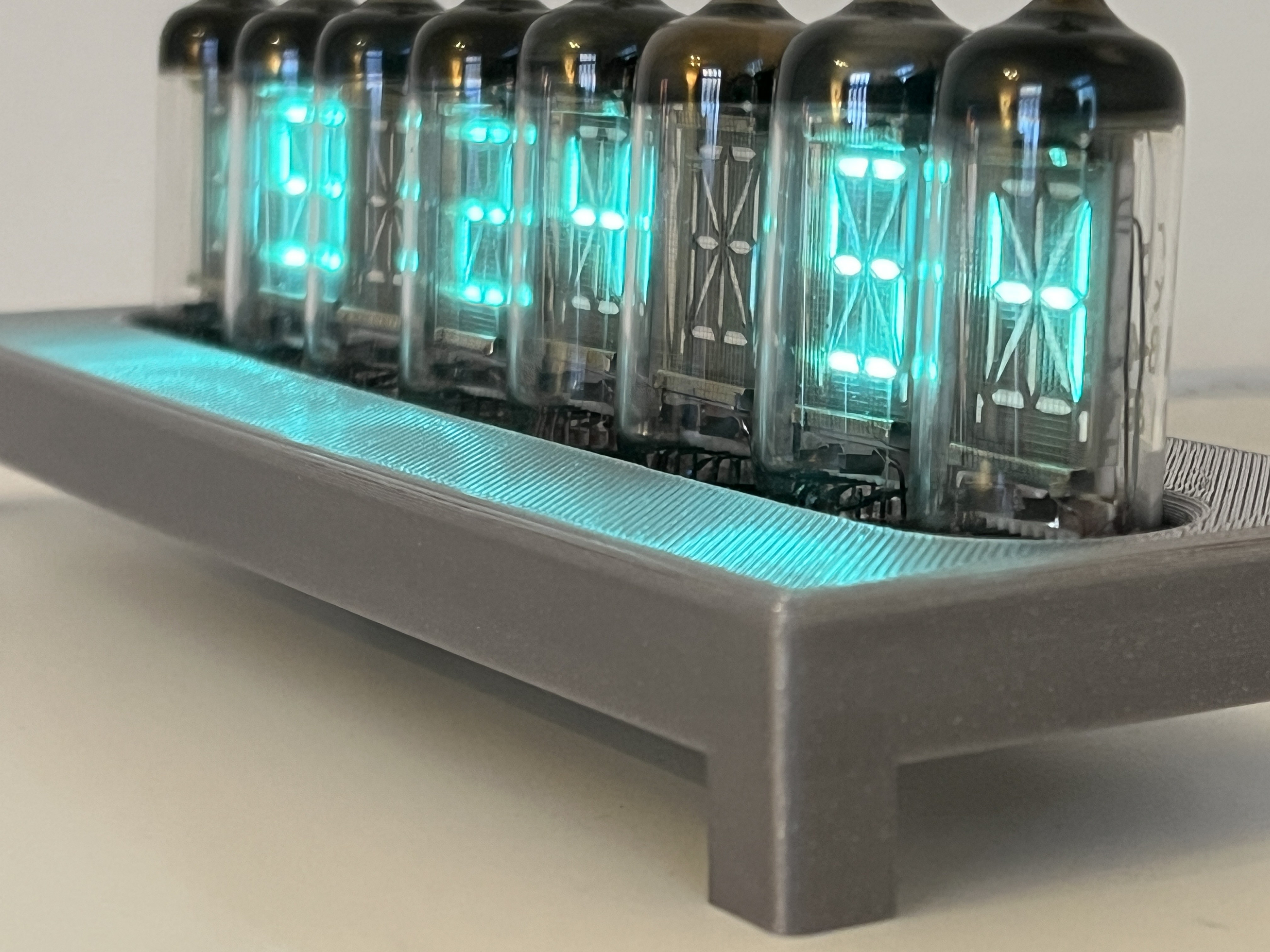
A clock built with eight authentic soviet vacuum fluorescent display (VFD) tubes, a custom designed circuit board, firmware and 3d-printed case
It is an evolution of Phalanx. Many of the firmware improvements made for Ameise also trickled down to Phalanx as its an unified codebase
Goals
- Everything that Phalanx has, plus...
- Text Display
- Better PCB design (ease of soldering, component choice)
- Better 3d printed case design
- Ability to display any message from external sources
Continue to see all the details!
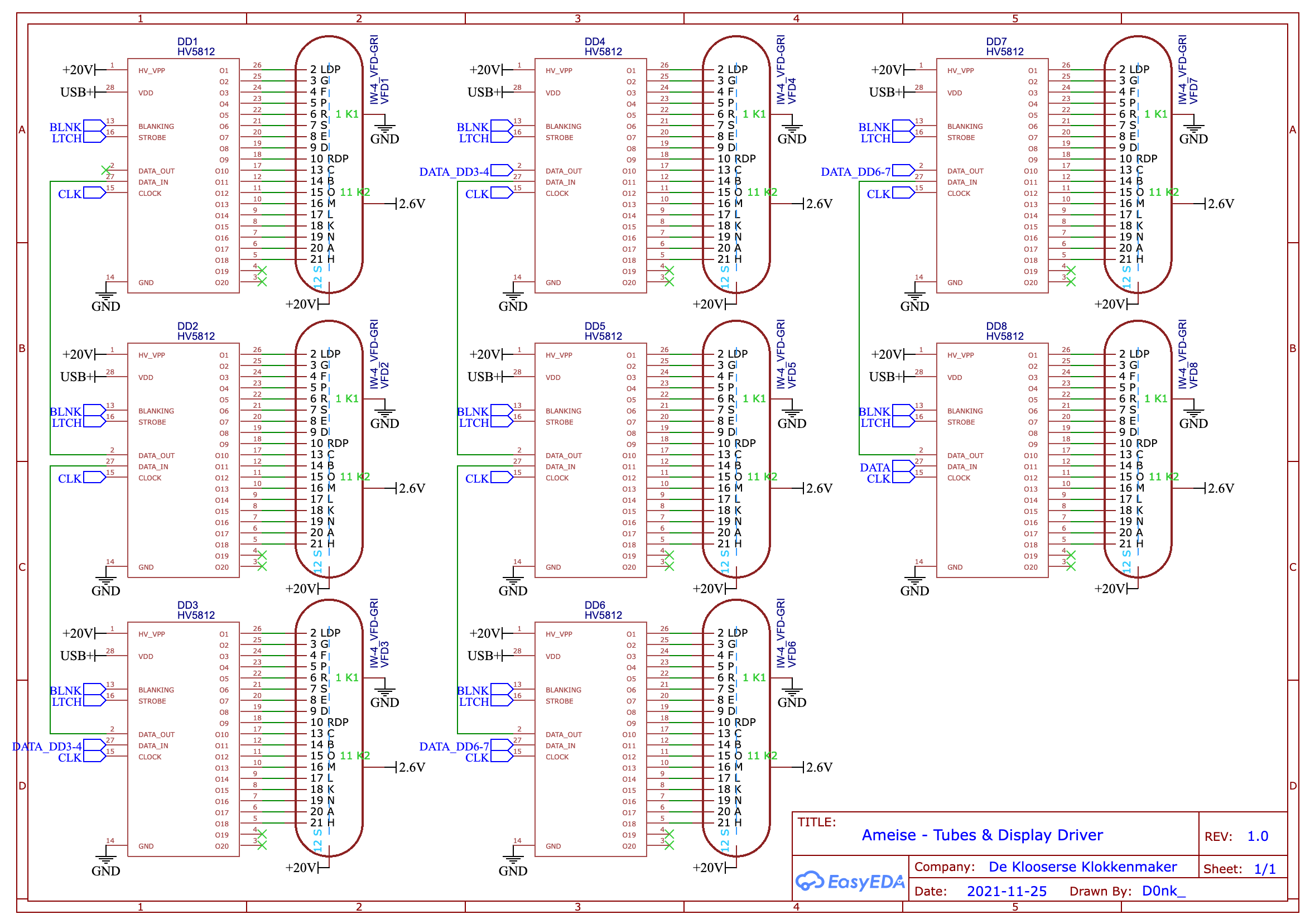
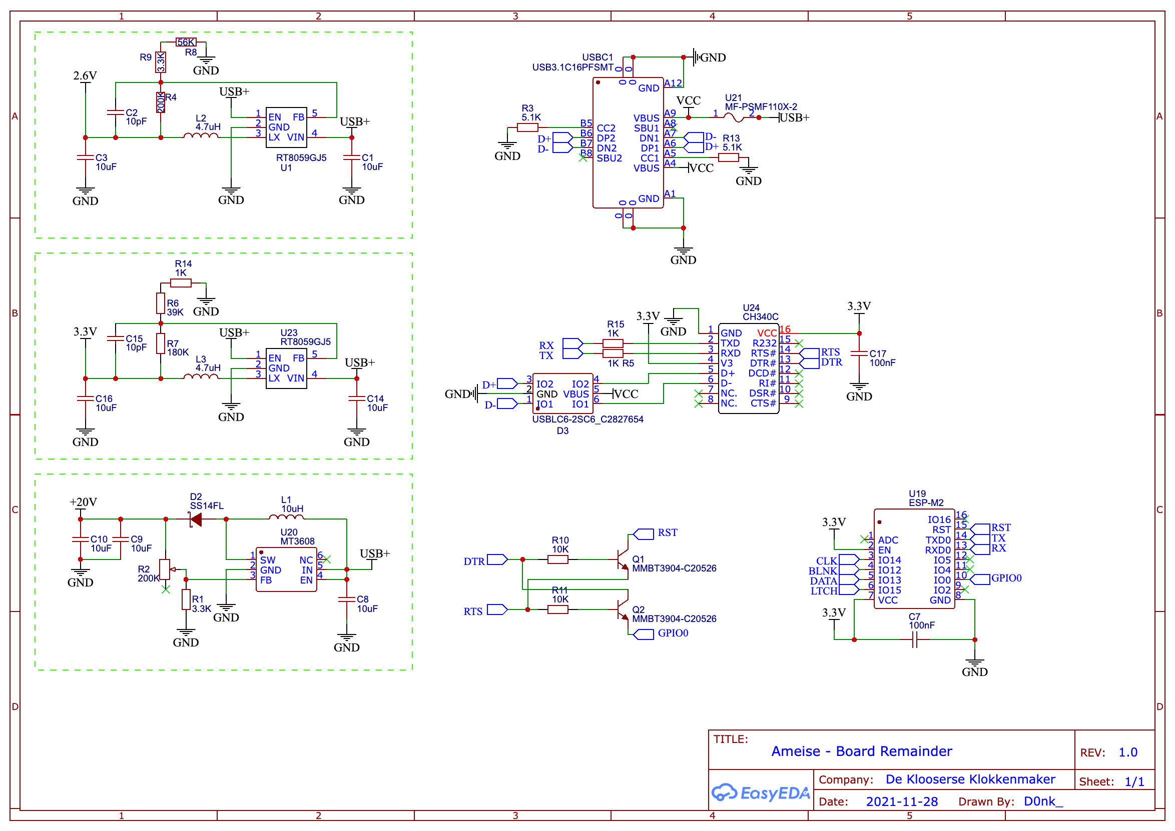
PCB
While Phalanx' design was largely cobbled together from other VFD projects online, here I needed to spend a bit more time to make sure I did not create any magic smoke.
The voltages were different, and the power consumption of IV-4 is higher than IV-6. Added to that there's also two more tubes. Fortunately the step-down and step-up regulators are well documented.
All the components were able to be soldered on one side, allowing me to make the case ±5mm thinner as well.
Firmware
Phalanx was quite simple in it's data storage. Every tube exactly fit in one byte, where each bit would be on/off for an individual segment.
Here the layout was a bit more difficult.
/*
    DisplayIV4 - Ameise
    - IV-12 is a 18-segment display (including dots), including 2 dead pins on the HV5182, we need 20 bits per tube.
    - 8 tubes.
    - -     0   LDP         10  B
   |\|/|    1   G           11  O
    - -     2   F           12  M
   |/|\|    3   P           13  L
   .- -.    4   R           14  K
            5   S           15  N
            6   E           16  A
            7   D           17  H
            8   RDP         18  Not Connected
            9   C           19  Not Connected
*/
For each digit, we'd need 2,5 byte, which is a bit inconvenient to deal with if we have to keep a sequential collection of bits.
Firstly, all possible characters in the ASCII table get defined
// const uint32_t[]
...
0b000101000000101000, //    88    X
0b000101000000010000, //    89    Y
0b010001010001001100, //    90    Z
0b000010010001010000, //    91    [
0b000100000000100000, //    92    backslash
0b010010000000010100, //    93    ]
...
uint32_t gives us 4 bytes to work with for data, but we are still only defining 18 characters here, since those are the only ones that matter.
The benefit of this notation is that all our "content" sits at the end of the 4 bytes.
Now that we have the binary data defined, we need to be able to get rid of the 1,5 byte of 'junk' data before we start sending it. and that half-byte is what makes it tricky.
To read how its done, check the code (InternalShiftDigit)
Additionally there is some support for text that is longer than the tubes allow + the ability to scroll it, but in the end everything goes through this conversion.
Companion App: Font DesignerA really simple Unity app which you can click on the segments to "draw" a character. This assisted greatly in making the font for the clock.
These could be copied straight into the header file in the 0bXXX format as shown in the previous section.
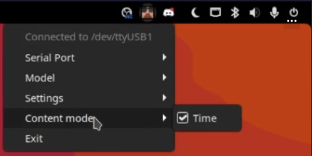
Companion App: Cross-Platform Tray
This was another rabbit hole I probably overengineered... but for fun!
The idea was to create a tray app that could run on Windows, Mac and Linux to override the device's internal device modes (displaying time, spotify time etc) for situations where you want to display content from things like a video game on the device.
To get this done, I ended up combining a couple of libraries on Github to make displaying the tray on each OS easy. Read more about this library here
The tray app is able to funnel various program's messages received through UDP network packets, and then transmit them to the desired device's serial port.
 Compatible programs are able to just spam the tray app with updates whenever they feel like it, but only the selected program will be transmitted to the device.
 One of the things I've used this for... Is with Final Fantasy XIV
It can perfectly make Ameise display things like your character's HP or names from selected NPC's thanks to goatcorp's Dalamud Plugin Framework.
Case
For the case, I switched from 123Design to Fusion360, and after a slight learning curve I was able to make the following model. It's not much more fancy than Phalanx' but that model turned out to be a bit skewed somehow so I wanted to focus on precision.

I found it very helpful to make a rough outline of the board to help test-fit everything and not have to go back to my calipers to measure the board again.
Additionally, the model now also has a bottom plate so it screws shut tidily, as if it's a proper manufactured product.
There's space for M3 screw brass threaded inserts, which are used to hold everything together.