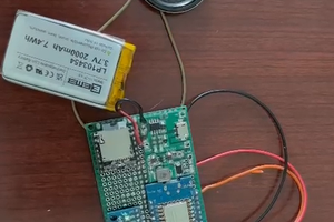
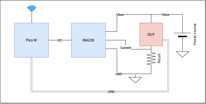
The aim of this project is to create an ultra-precise energy meter based on INA228 TI's energy meter device. INA228 is a 20-bit energy meter device, with I2C host interface capable of measuring voltage/current/energy at sampling rates up to 20Hz. The device is connected to a Raspberry Pico W host acquiring the data from the I2C interface and communicating with the host through the WiFi interface using a TCP protocol. In addition, the Pico-w module will be able to store IO level on DUT (Device Under Test) and transmit the data to the host application.
On the host side, a basic driver is implemented for libsigrok for communicating with the Pico W firmware and propagating the data to sigrok suite.
Pico-w is running a uPython firmware communicating with INA devices - acquiring the measurement data - gathering IO data and sending the data to the TCP client - connected to the acquisition port (default port is 5555).
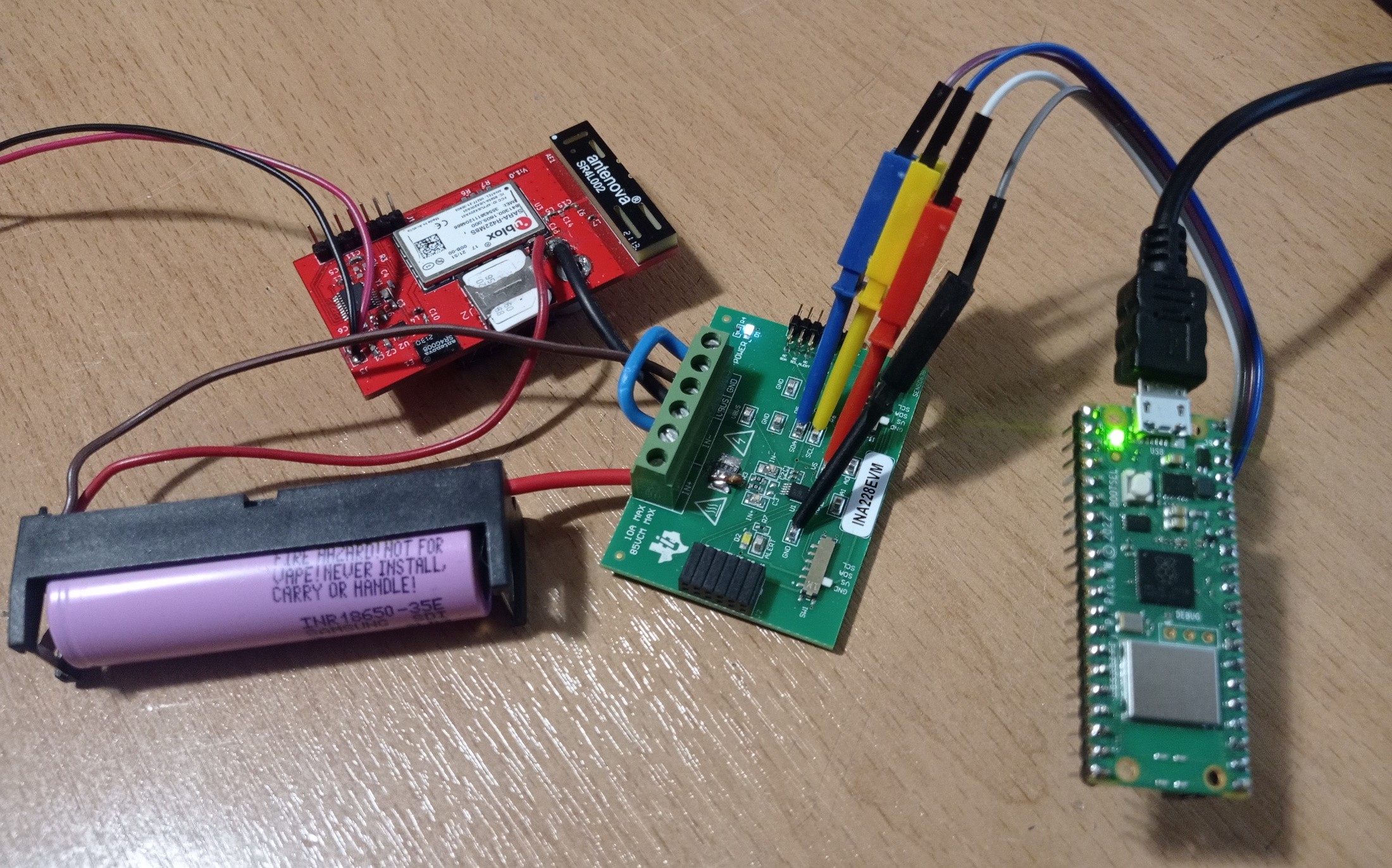
Following snapshots from a working prototype - using INA228EVM connected to rpi Pico-w module and FW based on sigrok suite.
Prototype test setup - connected to IoT DUT device:
Device connection to sigrok:
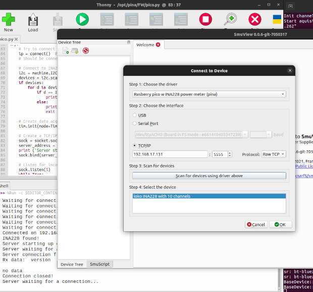
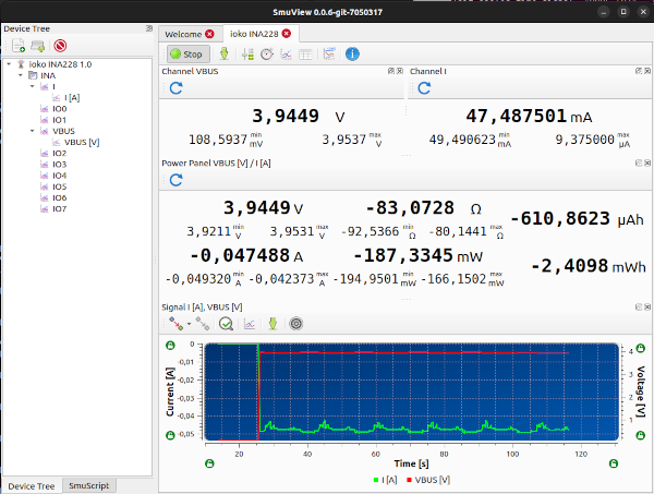
Data capture to smuview:
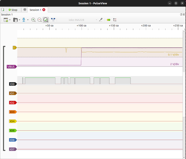
Data capture to pulseview:
Next steps:
- Support multiple INA devices
- Design Pico-W board supporting multiple INA devices, IOs, shunt switch
- Capture Pico-w ADC inputs
- Add configurable power supply outputs
- Improve configuration support
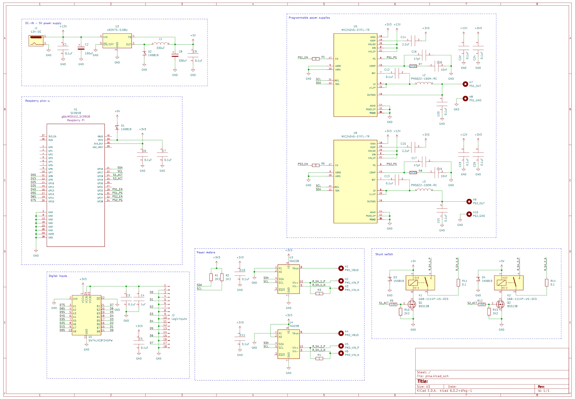
Initial schematic design:
Schematic design for PINA board, having 2 Energy meter channels with shunt switches - providing up to 4 current measurement range in total, 2 programmable power supplies - capable to provide more than 3A and 0.65 to 5.5 Volts, pico-w socket and on-board level shifters for the logic analyzer inputs:
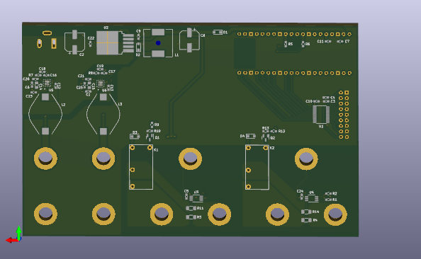
PCB preview:

 Daphne
 Maria Carlina Hernandez