deʃhipu
-
New Body in Action
08/26/2023 at 22:53 • 0 comments![]()
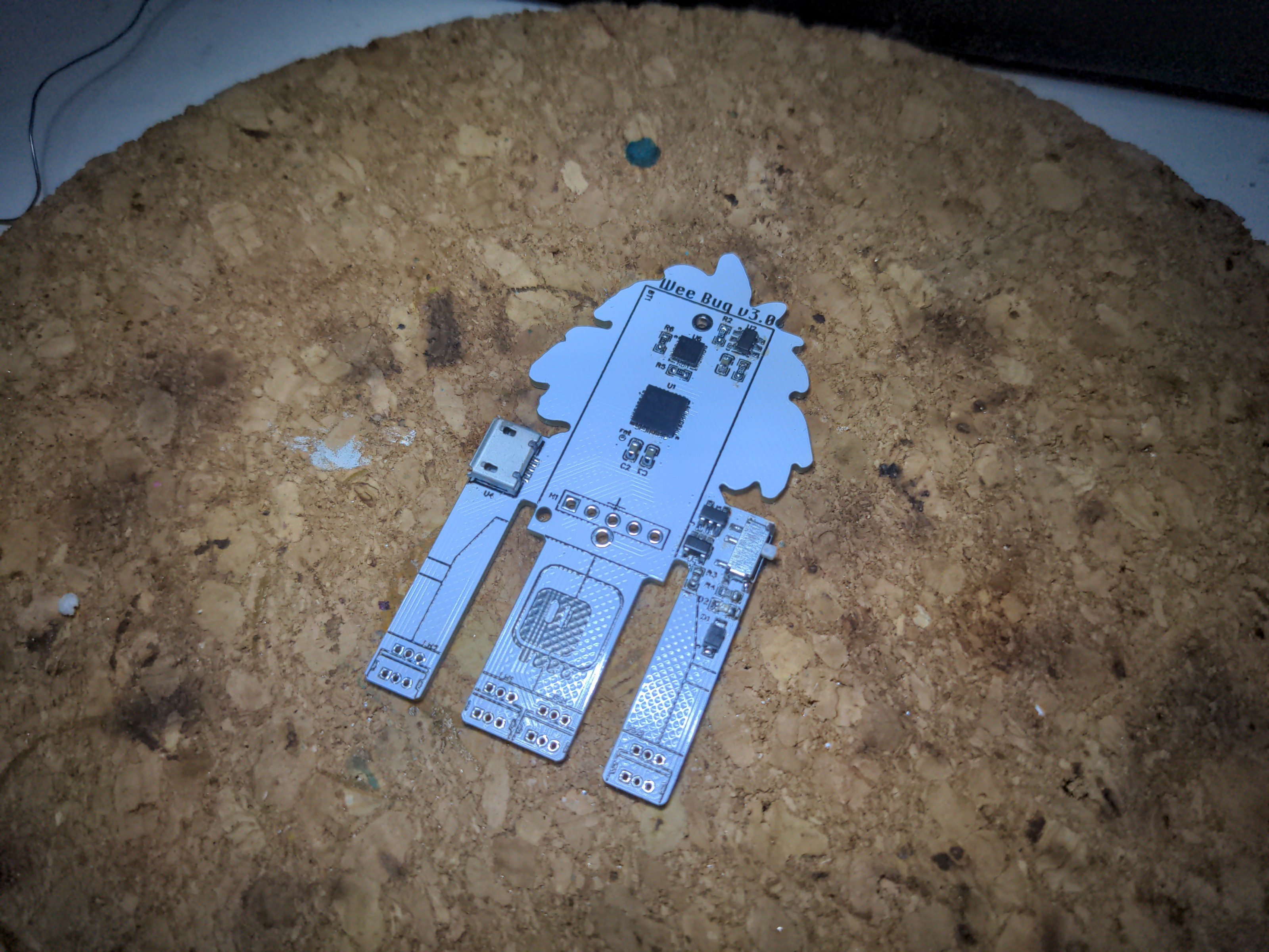
As always, the PCBs arrived from JLCPCB, so I went ahead and assembled one. I had some fun soldering the accelerometer chip – it's QFN, but it was lying in my drawer for a few years, and apparently some of the pads got oxidized. Only after I went over them with a hot iron and flux, the soldered correctly. Good thing I decided to test the chip before I soldered the battery holder, because the chip is underneath it, and it would be a pain to have to desolder the holder first. Also, I was afraid that the THT servo sockets will be hard to solder on both sides of the PCB, but turns out they are far away from each other enough to not interfere with soldering. Phew. I still don't think I could make a fab do this, so if I ever decide to do a workshop with this robot, I will have to switch to SMD sockets.
![]()
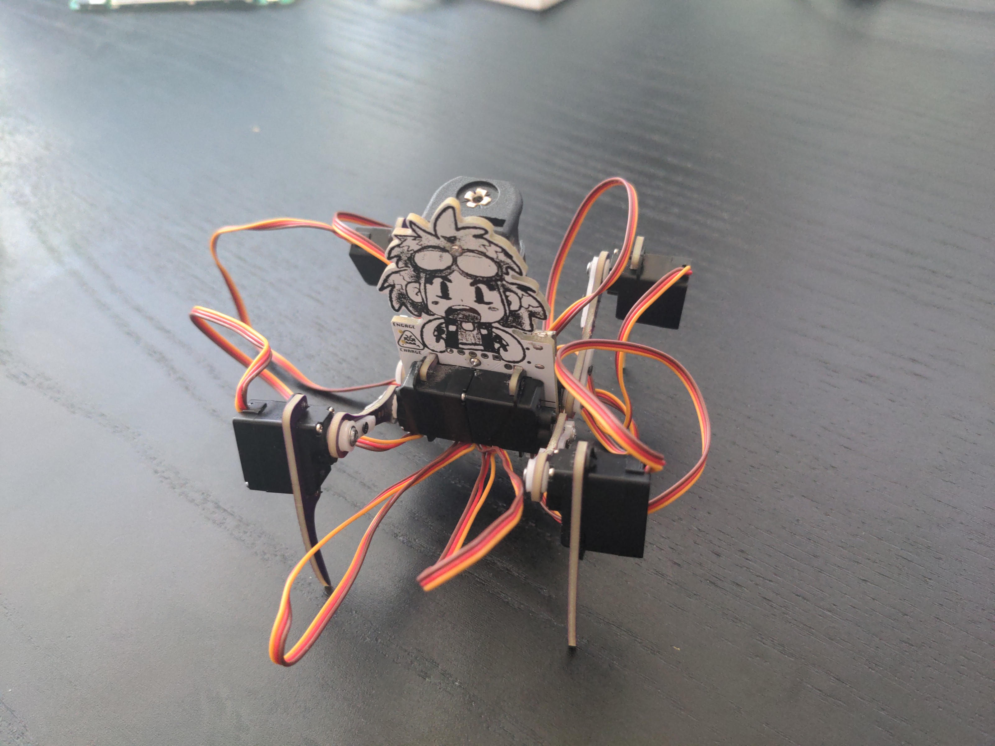
After it was all soldered, the UF2 bootloader flashed, and CircuitPython firmware uploaded, it was time to assemble the legs. And here's the first mistake: I made those long slots in the PCB hoping that I will be able to stuff at least some of the servo cables in there, to make it look a little cleaner. But I didn't anticipate how small this PCB is, and the cables simply don't fit in there. Oh well. If I ever make another version, I will remove the slots, leaving only the parts necessary for servo mounting. That will also make routing of the traces easier.
![]()
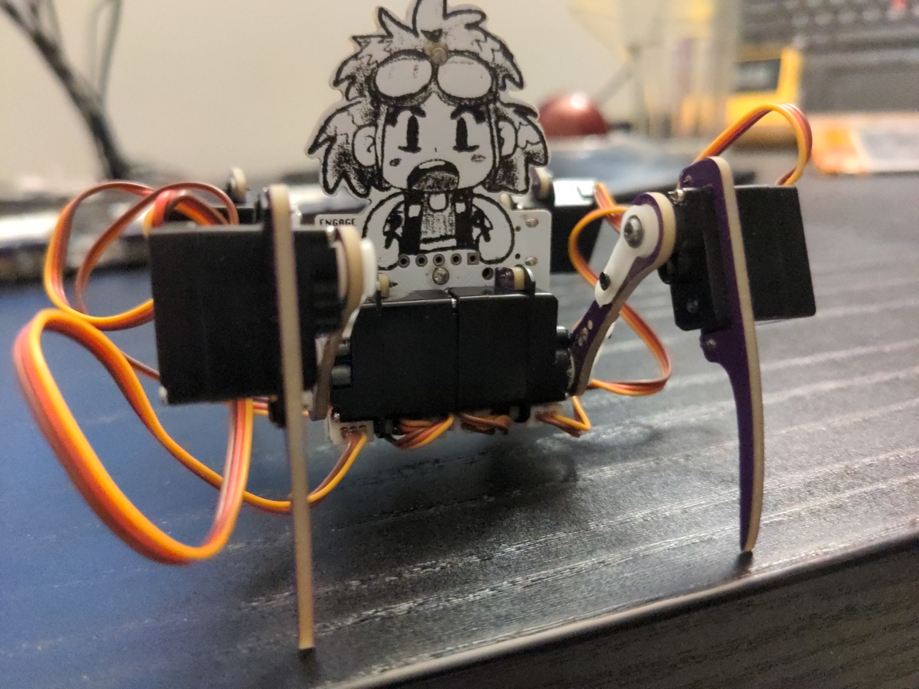
With the legs connected, the servos zeroed and the initial leg positions calibrated, I copied some of the old code for walking (the SAMD21 build of CircuitPython doesn't include async functionality that my newer code uses), and it walks. I just had to change the order in which the legs are initialized, so the right timers get assigned to their PWMs. However, I found further mistakes.
First of all, the switch that switches between walking and battery charging is reversed, so the labels are wrong. Not such a big deal, I suppose, and I could easily enough fix it by swapping the labels.
I also thought that I made a second mistake, connecting the USB power so that it powered the servos, but that was just a mistake in soldering the shottky diode in reverse. After flipping it, the servos are now correctly only powered from the battery, so I can program the robot when it's switched to charging mode, without worrying about it making random movements.
The next steps now may involve using the accelerometer for interesting things, doing something about the cables (I need to open one servo and see if I can easily shorten the cable from that side), and seeing if I can enable async on this build, possibly at the cost of disabling some of the built-in modules that I'm not using.
-
New Body
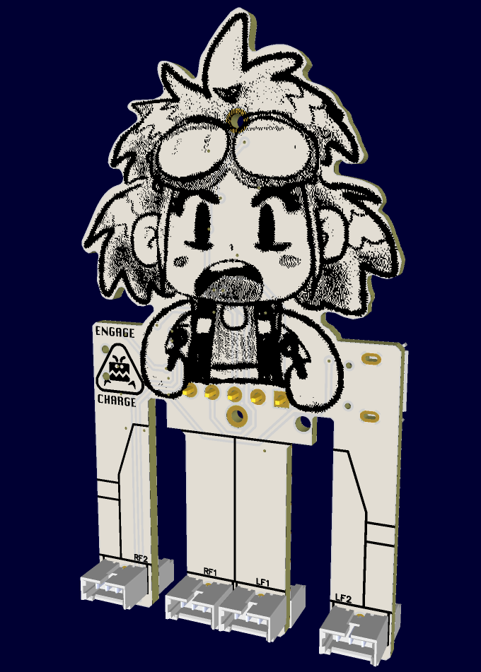
08/18/2023 at 23:34 • 1 commentI couldn't sleep last night, and when I can't sleep I design PCBs. This time I decided to get back to this little cute robot and make a new PCB for its body. The original one was kinda slapped together without much deliberation, just to make it look like its bigger brother #Fluffbug but fit the small servo sockets. This time I decided to do it properly.
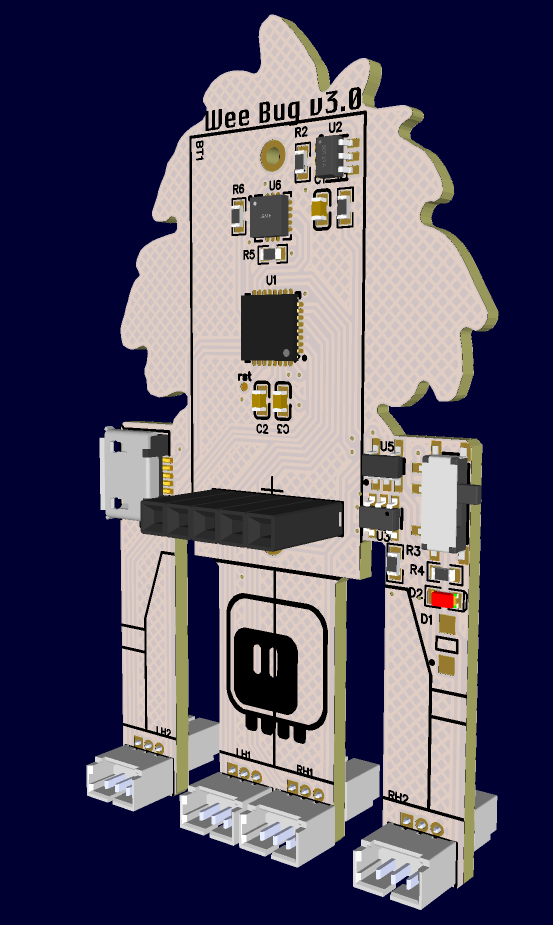
First of all, I want some solution for the cable management. I can't use IDC plugs like with Fluffbug, because the wires those little servos use are so thin! But I also don't want to have to re-crimp the plugs after cutting the wires to the right size. So I decided to compromise by adding slots to the PCB under the servos, where you can hide excess wires. Hopefully they are large enough to fit all of them.
Second thing is to give up on the Xiao board, and use a discrete microcontroller chip right on the board. That lets me use all the pins, makes the whole thing smaller, and, if you assemble it yourself, also cheaper. It has the downside that you can't easily replace the code by changing the modules. Oh well.
![]()
And finally, the most visible change is to add some visual bling. This robot looks a little bit like a crab, and I could have leaned into it, but while I personally think crabs are incredibly cute, many people don't agree with me, especially the ones with some arachnophobia. So I decided to make it look like a mech from an anime movie or game instead, by adding a picture of a pilot on the front of the PCB.
![]()
Last, but not least, I added an accelerometer chip in there, so that we can have some sensors to react to. The board should arrive in a week or so, and I will probably take some time assembling it. I will keep you updated.
-
New Servos
06/14/2023 at 09:00 • 0 commentsI like the tiny robot very much, but I didn't publish the design files for it, because the Hobby King servos I used for it are discontinued and you can't buy them anymore. But then I went to Aliexpress and searched for 2g sub-micro servos, and lo and behold, there is a whole bunch of them out there. They don't have a model number – all they tell you is that they have POM gears and 260° range of motion. And one of three kinds of plugs to choose from. They are slightly more expensive than your regular 9g servos, at about $2, but still very cheap. So I decided to go ahead and try to make another WeeBug with them.
![]()
Oh, right, and they are black instead of white. So I got purple leg pieces this time around. I also used a slightly different battery holder, but it didn't require any modifications.
Now how do the new servos work?
Wow, they are fast! Much faster than the white ones. During calibration I had the robot literally jumping on the table when the legs adjusted their positions. I think I will be able to make this one scuttle around much faster than the white one.
![]()
Other than the speed, I don't really see much difference. They have enough torque, and I'm only using the standard 180° range of motion anyways. There is no noticeable jitter or other problems.
One difference is that those servos don't come with mounting screws, so you will need some screws of your own to attach the servos to the leg pieces. I also made the holes in the leg pieces too small, so some rimming/dremelling was necessary to make the servo horns and the screws fit correctly.
I will be fixing those mistakes, and then I will publish the design files.
-
Just Programmed
03/01/2023 at 22:00 • 0 commentsI have finally "just" programmed it. It took me some time, because I had the pins on the left side of the robot completely mixed up, and I wasted time trying to guess which one is which (and which one needs reversing the servo) purely by watching them move while walking, which is, in hindsight, pretty stupid. Moving the servos one at a time worked much better. It's now walking, and has the code needed for receiving commands.
![]()
Now I "just" need to add the code for reading the tv remote codes, and/or the gesture sensor, and I should be good.
-
Now Just Program It
01/26/2023 at 22:02 • 0 commentsThe last part that was missing - the battery - arrived yesterday, so I was able to verify that everything works so far. Unfortunately, the servos come from two different batches, and some of them rotate in opposite directions. I could fix that in hardware by just opening them and swapping the leads to the motors, but I think that I will instead make the code a little bit more flexible, add a Servo class and allow inverting each of the servos individually. It's also possible I got some of the pin numbers swapped around – I need some quiet experimenting time to figure it all out, and also to fine-tune the trims on the servos and so on.
![]()
-
2.0 Already!
12/31/2022 at 19:44 • 0 commentsI looked at my PCB design today with fresh eyes, and I found a mistake in how the power is routed, which would require a bodge. So I used that as an excuse to re-design it with the 14250 battery holder, which also made it much smaller. And since you can add designs to an existing order in JLCPCB, I did just that. So the 1.0 version will be obsolete on arrival, sadly, but I will get to build a much smaller robot.
![]()
![]()
I also went ahead and designed a PCB for the mechanical parts of the legs. I was lucky to not get hit by the panelization penalization, but it's fine for a one-off design like this. If I were making more units, I would go for laser-cut parts instead.
![]()
-
PCB Design
12/30/2022 at 23:29 • 0 commentsI measured the servos, and quickly designed a PCB similar to the one used in #Fluffbug, but proportionally smaller.
![]()
I gave up on the IDC connectors for the servos, and just went with the 1.25mm JST sockets. Instead of the Lolin S2 Mini, I decided to use either the Adafruit Qt Py board, or Seeedstudio Xiao – as it happens, they have the same pinouts, so I can decide later, or even switch between them. All the rest is pretty much the same as in Fluffbug, but since there was some free space, I also added a footprint for an optional infrared sensor, so that I can use a tv remote to control the robot.
The last problem is the battery. I didn't want to use the pouch lipo batteries, because they are not standard and pretty dangerous, so I looked at what standard battery size would fit it. Eventually, I decided on LIR2450 (or the bigger LIR2477 version), and added a coin cell battery holder to the PCB. The contacts stick out a bit, but I can just cut them.
![]()
Of course as my luck has it, as soon as I ordered the PCBs, I found out the perfect battery size that would make it look exactly as Fluffbug, only smaller: the 14250 cells. There is even a holder for it that looks identical to the one in Fluffbug, just smaller:
![]()
Just look at how cute it is! In the end, I decided to order some of those cells and holders as well, and I will try to bodge them on the PCB somehow.