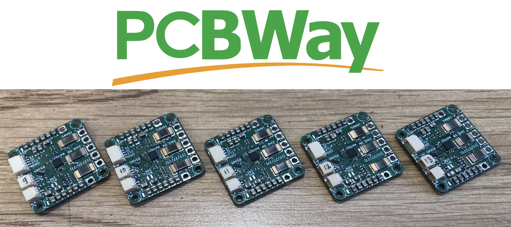
Thank you to PCBWay for finding this project on here and offering a sponsorship! A majority of the cost of this revision, including the boards, components, and assembly, are paid for by PCBWay. Saves me a lot of time placing the components by hand!

This version is shorter, has an external SPI port, and NTC thermistor port. I don't have the firmware completed for external SPI and the thermistor, but I'll post another update if my project requires them (very likely the thermistor).
Changelog from v2 to v3:
- Fixed TVS diode direction on VBUS (!!)
- Changed to 37x 22uF ceramic capacitors instead of 2x 100uF electrolytic capacitors for a thinner PCBA
- Removed I2C (formerly on PB6 and PB7)
- Moved UART_TX and UART_RX to PB6 and PB7 (formerly on PA2 and PA15)
- Changed PA2 to ADC1 CH2 to read a 10k NTC, soldered to pads
- Changed PA15 to GPIO for external SPI CS (MAG2_CS)
- Added 13.7k pulldown on SPI_MISO to keep it determined when no devices selected
- Changed to 100nF filter capacitor on BUS_SENSE instead of 1nF to charge ADC capacitor better and for smoother data
- Changed BUS_SENSE gain to 5x instead of 5.12x to reuse 13.7k resistor
- Removed test point on BUS_SENSE
- Added test point on LED_STATUS (for debugging using GPIO)
- Removed NRST pushbutton to create space
- Added 6 pads with 0.5mm pitch to solder FFC cable for an external SPI encoder
- Changed vias to 0.25mm hole size and 0.55mm plated diameter instead of 0.2/0.5 for easier manufacturability
- Changed minimum track clearance from 0.2mm to 0.16mm to make space for larger vias
- Changed to equal number of vias (27) on the top side of all three shunt resistors
- Changed most silkscreen text to 0.8mm width/height
- Put all footprints and 3D models in project library O32controller
 Christopher Xu
Discussions
Become a Hackaday.io Member
Create an account to leave a comment. Already have an account? Log In.