 Max Olender
Sign-up for pre-orders at https://maxlab.io/store/edge-ai-camera/
For more cool projects, visit maxlab.io.
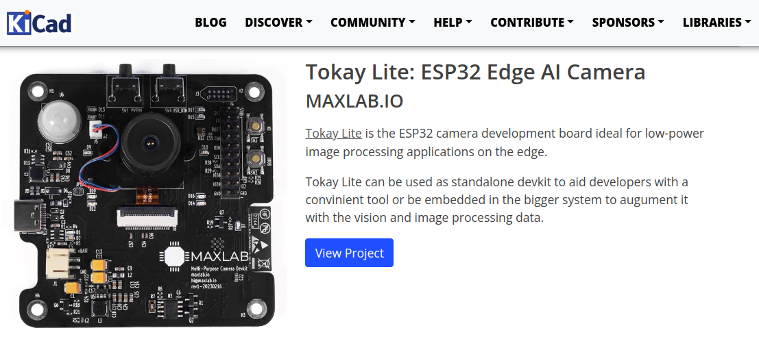
Battery-powered IoT camera with nightvision, motion detection and TensorFlow Lite support
Already have an account? Log in.
To make the experience fit your profile, pick a username and tell us what interests you.
Sign-up for pre-orders at https://maxlab.io/store/edge-ai-camera/
For more cool projects, visit maxlab.io.
ai-camera-rev2.pdfRev2 schematics designAdobe Portable Document Format - 1.25 MB - 06/06/2023 at 20:09 |
|
|
I'm late announcing this, but Tokay Lite will be launched soon on CrowdSupply platform!
Soon, I hope, it'll be available for preorders :)
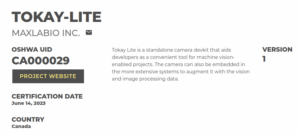
Another nice accomplishment is that the camera is now officially certified under OSHWA:
https://certification.oshwa.org/ca000029.html
It turns out the KiCAD webpage contains a nice list of Open Hardware projects. Why not publish the camera there? Check out this and other awesomeness by checking "Made With KiCAD page": https://www.kicad.org/made-with-kicad
It was a quite long time since the project was published and I finally found time to declare that the camera indeed works!
I'll put some neat details soon into a separate post.
For now, I humbly suggest you to answer a couple of questions on what is most interesting you found in this camera project?
Here is the link to the questionnaire: https://docs.google.com/forms/d/1TgMNURF4EbG6NompMk4GUfnyDWk0rIznlREFTz6PEmM
Thanks!
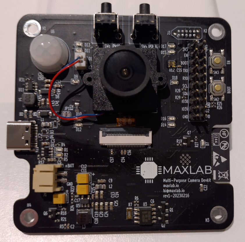
As expressed before, revision 0 of the camera works and is functional but requires some fixes.
The new revision 1 is complete, and now it is received from JLCPCB.
Speaking of JLCPCB....
A usual way JLCPCB marks LEDs are "+" and "-" in their DFM checker.
As far as I understand, JLCPCB uses the silkscreen to double-check the proper orientation in addition to CPL files.
I'd prefer them to check the fab layer, but for whatever reason, they hesitate to process additional layers except for copper, silk and edge. If you know why it is so - please let me know here.
However, for some reason, they labelled IR LEDs with "C" (collector) and "E" (emitter). I wasn't paying enough attention, approved the order, and received boards with wrong IR LEDs orientation.
Luckily that's not a big deal, so resoldering them worked great. Not counting one lost LED I accidentally broke with my solder iron.
IR LEDs picked up by my phone in the dark:
The picture with the IR illumination:
Sadly, the new revision (rev1) arrived with LEDs in the wrong polarity. JLCPCB messed this up, and I need to resolder them all again.
Unexpected current paths are always underestimated when multi-power systems are designed.
The rev0 wasn't the exception.
The camera PCB contains battery input, USB input and the power switch to disconnect the battery when USB is connected:
The power switch switches off the battery if a voltage is present on its gates. When the USB is disconnected, no voltage should be applied to the switch gates. The switch is then turned on, allowing the battery to power the system.
Turns out that when the camera is connected to a battery and USB is disconnected, the internal ESP32 USB pull-ups provide a current that flows through ESD diodes into the USB power rail and into the power switch:
The voltage on the power switch gates was large enough to put it into the linear mode, significantly increasing its internal resistance. And as soon as the power-heavy transmission started, the power switch dropped too much voltage, and ESP32 went to brownout reset.
Dave from EEVBlog has a great video about phantom currents, so make sure you're prepared for such kinds of bugs:
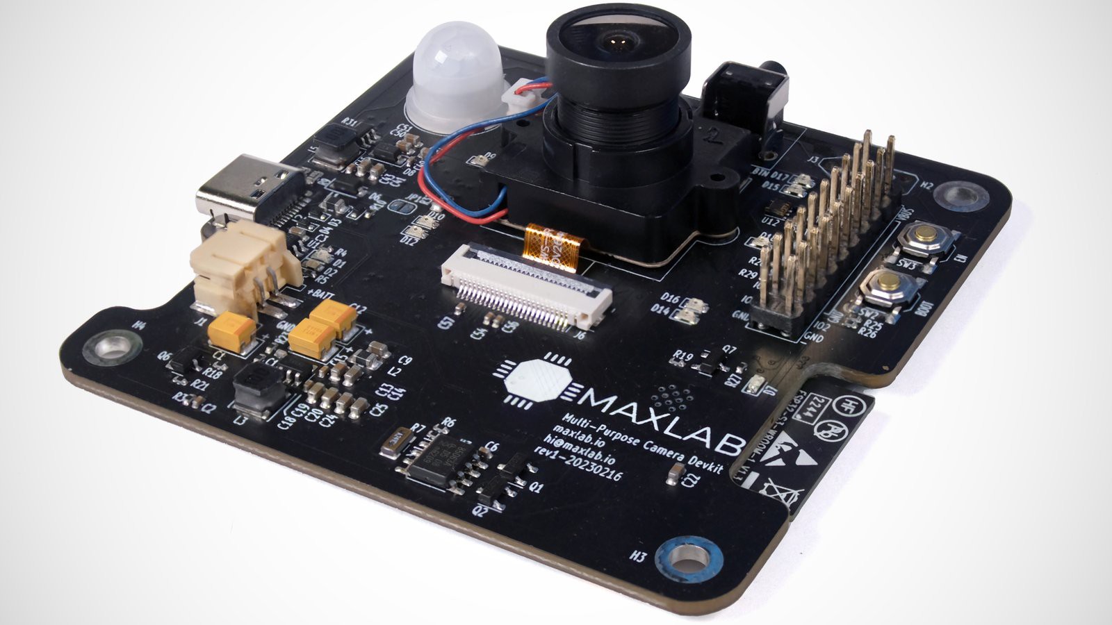
So with rev1 I decided to go with 5V TVS that do not tie USB power rail with data lines and it worked great:
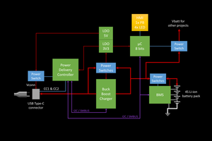
I decided to go with USB-C in rev1: it's a modern way to power stuff, and ESP32 is a power-hungry beast when transmitting, so having extra power margin on a source end wouldn't hurt.
However, implementing the full-featured PD wasn't on my list of things, so I decided to go with "dumb" power advertisement via resistors on CC1/CC2 pins.
You may find 5.1K resistors on CC pins in the vast selection of boards there, but pay attention that this scheme isn't fully compliant.
The power sink (in case it's our camera) must monitor the voltage levels on CC1/CC2[1] to understand whether the source can actually provide the currents required:
So simply putting resistors on the CC1/CC2 isn't enough.
On the other hand, the majority of boards work like that (without any monitoring), and all of my ESP32 pins are used up, so... I decided to go along with the ignorance and abandon the monitoring.
My previous experience says that it works fine when paired with the proper power adapter (users...
Read more »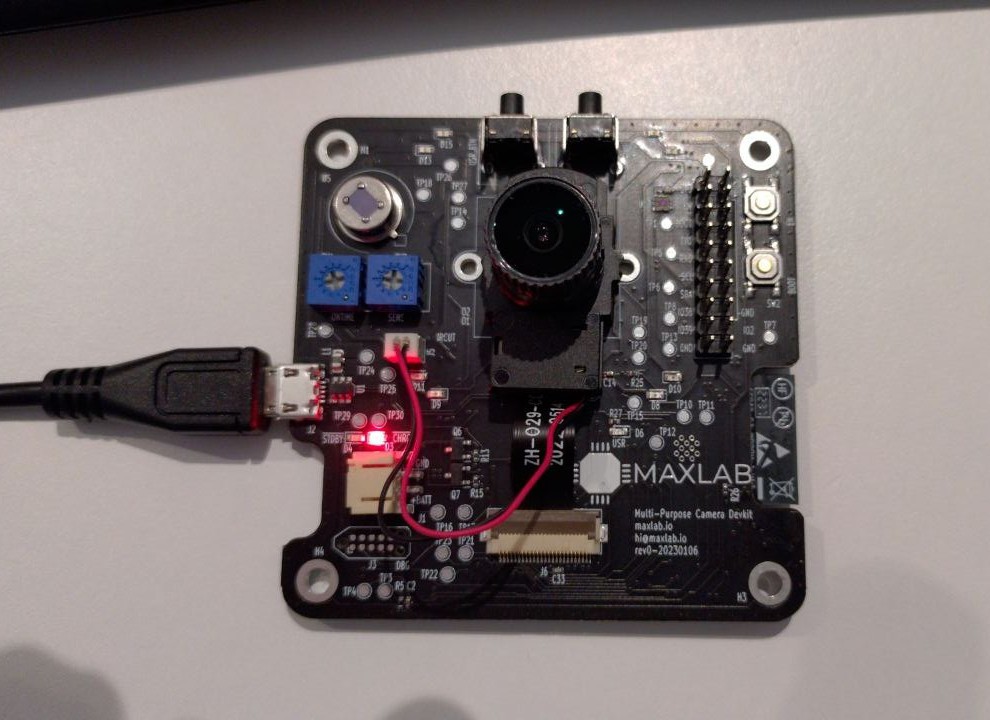
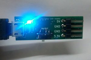
JLCPCB did a great job, as always.
Quite a list of things to test, but USB, JTAG and CDC seem to be working fine:
[27615.070318] cdc_acm 5-3.2:1.0: ttyACM0: USB ACM device
[27615.451032] usb 5-3.2: USB disconnect, device number 122
[27615.803839] usb 5-3.2: new full-speed USB device number 123 using xhci_hcd
[27617.497138] usb 5-3.2: new full-speed USB device number 124 using xhci_hcd
[27617.726271] usb 5-3.2: New USB device found, idVendor=303a, idProduct=1001, bcdDevice= 1.01
[27617.726276] usb 5-3.2: New USB device strings: Mfr=1, Product=2, SerialNumber=3
[27617.726278] usb 5-3.2: Product: USB JTAG/serial debug unit
[27617.726280] usb 5-3.2: Manufacturer: Espressif
[27617.726281] usb 5-3.2: SerialNumber: F4:12:FA:E8:62:6C
By the way, did you know that ESP32S3 and IDF have built-in USB peripheral support with JTAG and a console? So you no longer need to keep auto-flashing circuits on your ESP32 boards. More information here:
https://docs.espressif.com/projects/esp-idf/en/latest/esp32s3/api-guides/usb-otg-console.html
https://docs.espressif.com/projects/esp-idf/en/latest/esp32s3/api-guides/jtag-debugging/index.html
Good start, nevertheless. Stay tuned!
At this point, all project files are submitted to jclpcb and I hope to receive our board within a few weeks!
Meantime, there is a lot of work on the software side of things.


Re-posing here from the chat:
The BOM optimization is still in progress, so I would like to refrain from posting the final figure :)
I'll let you know when I finish testing and the new revision.


 Kuldeep Singh Dhaka
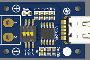
 electronicsworkshops
 Stefan Wagner
Your project very interesting , how much costing you per board?