 George Gardner
To make life easier, I modeled and printed a winding jig that supported the standard 608 bearings, along with a holder for the drill
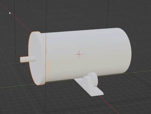
The part that attaches to the drill also contained an actuator that contacts a microswitch for counting revolutions. This was attached to a mechanical counter.
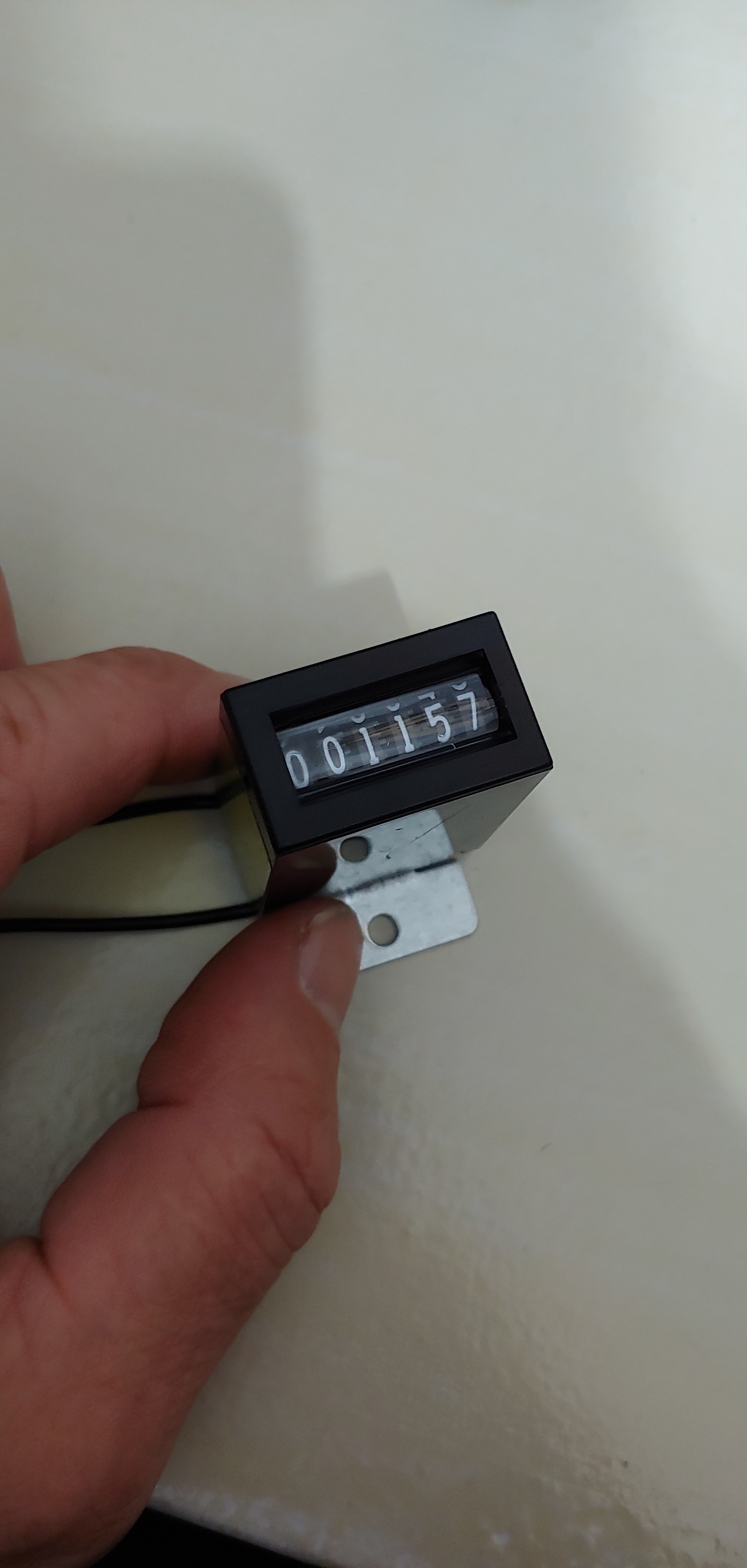
After the coil was wound (timelapse below) I used some brush on polyurethane. The counter didn't work as I intended, as I forgot to solder the wires and they became disconnected during the process. I was shooting for approximately 16.8 inches of winding, but ended up adding another inch or so, as I planned to remove some of the lower threads and cut the bottom to height. After the below video, I ended up winding another secondary. The reason being was the poly had just come from the garage and was cold and thick, which made for a very unattractive appearance. On the second coil, I used kapton tape around the base and top so the poly would not distort the clean look of the plexiglass form. In addition, I ended up soldering the wires to the counter and ended up with 1,180 turns. This number will decrease, as I plan to remove the first few windings at the bottom.
Discussions
Become a Hackaday.io Member
Create an account to leave a comment. Already have an account? Log In.