 George Gardner
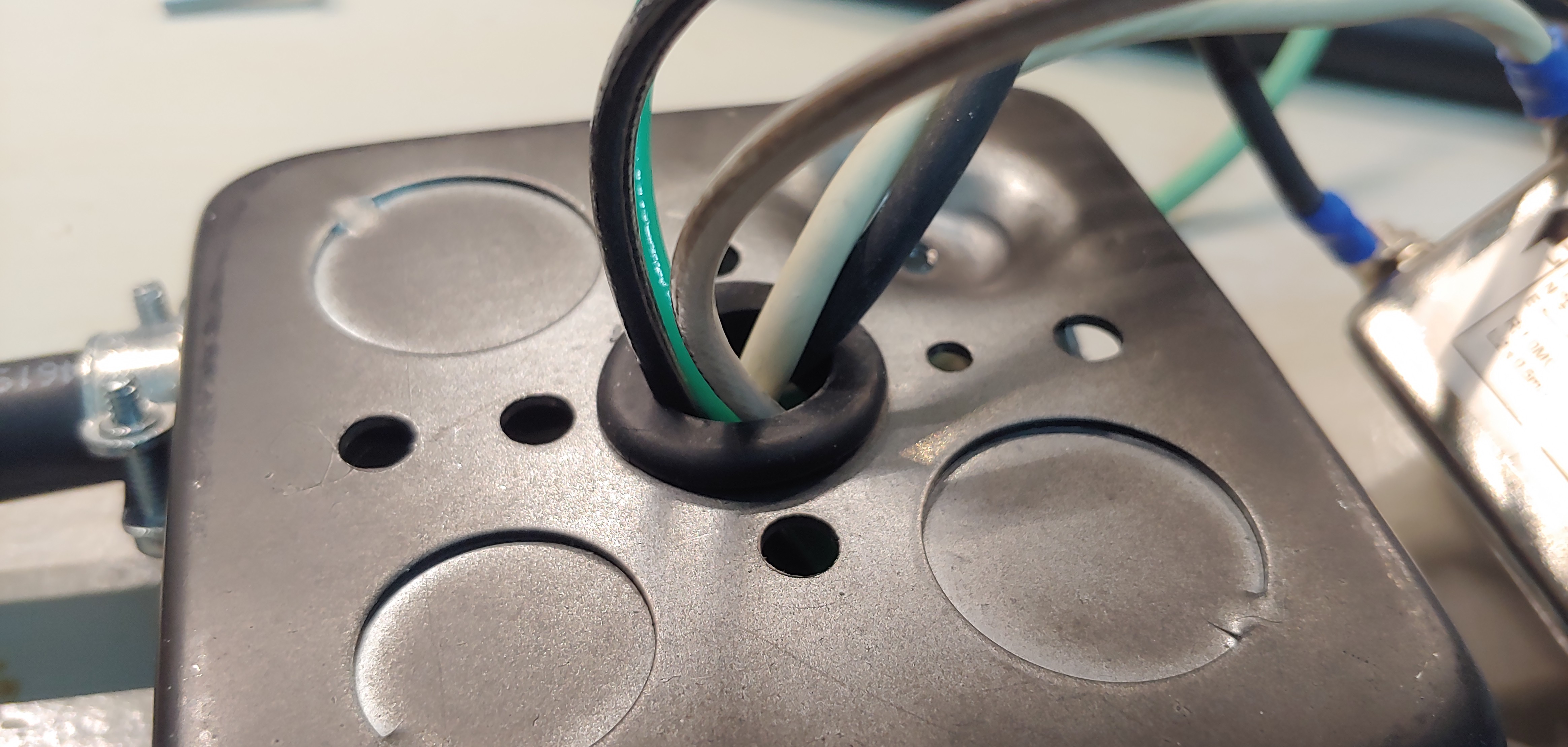
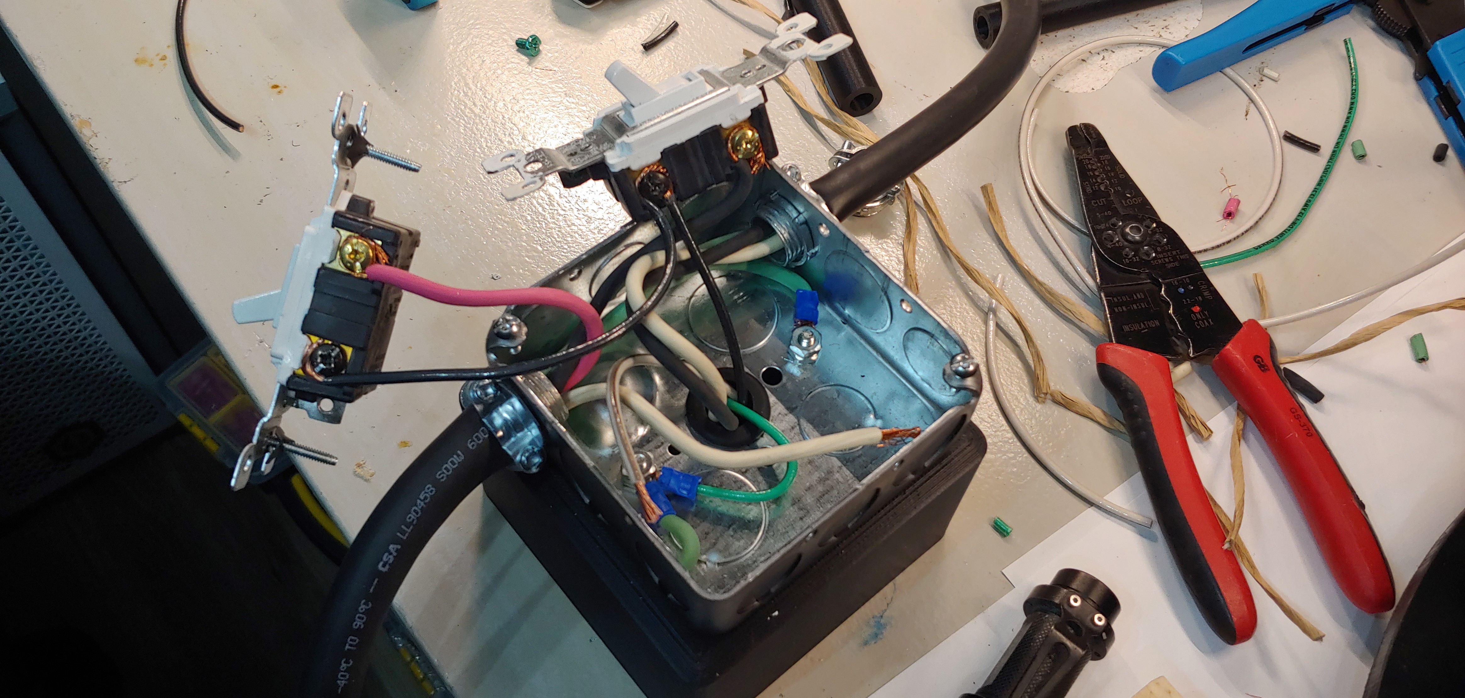
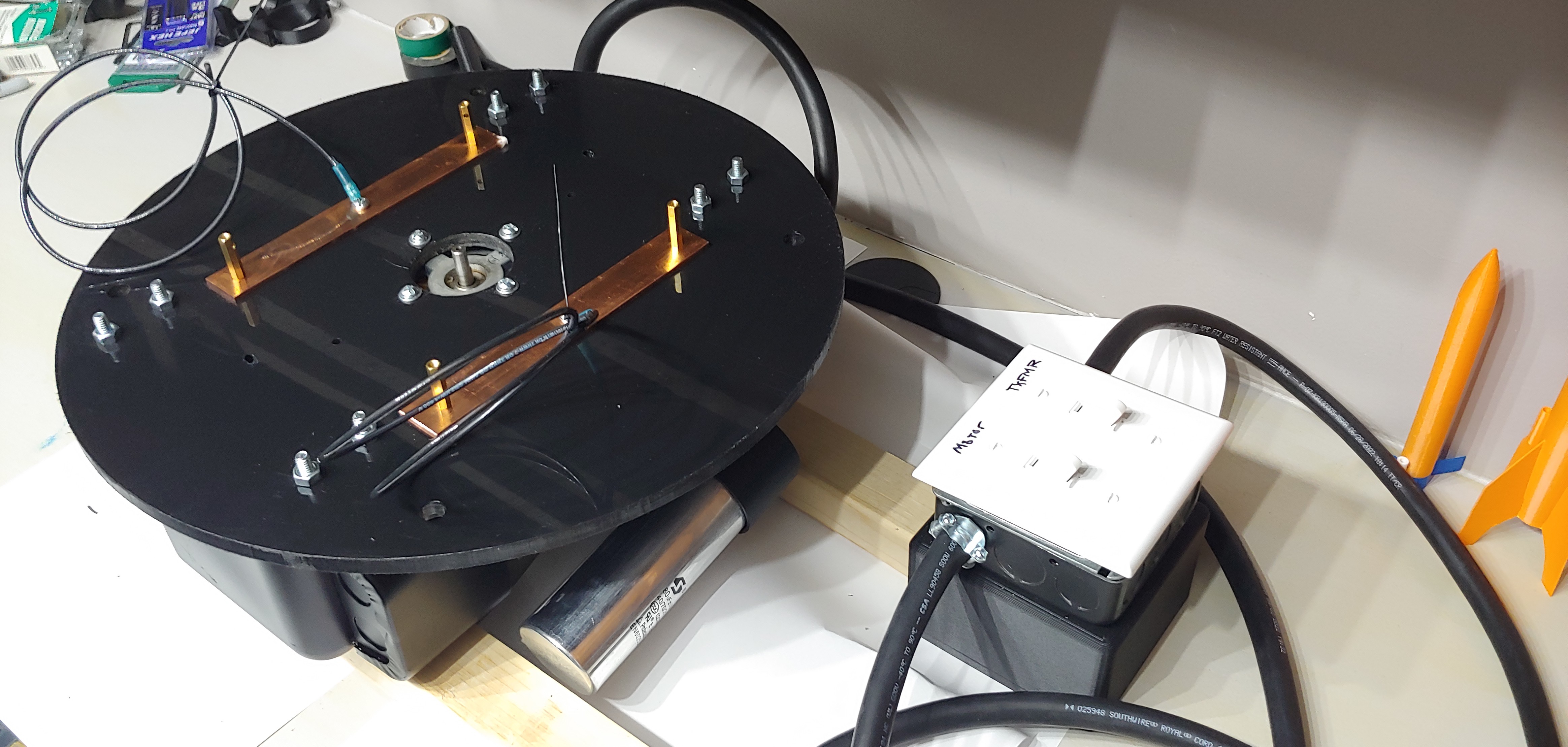
Tonight I continued down the supply side, adding a 1900 box with switches and an EMI filter. I printed a custom case for the EMI filter that attaches to the 1900 box, then used a grommet to bridge the wires between the two.
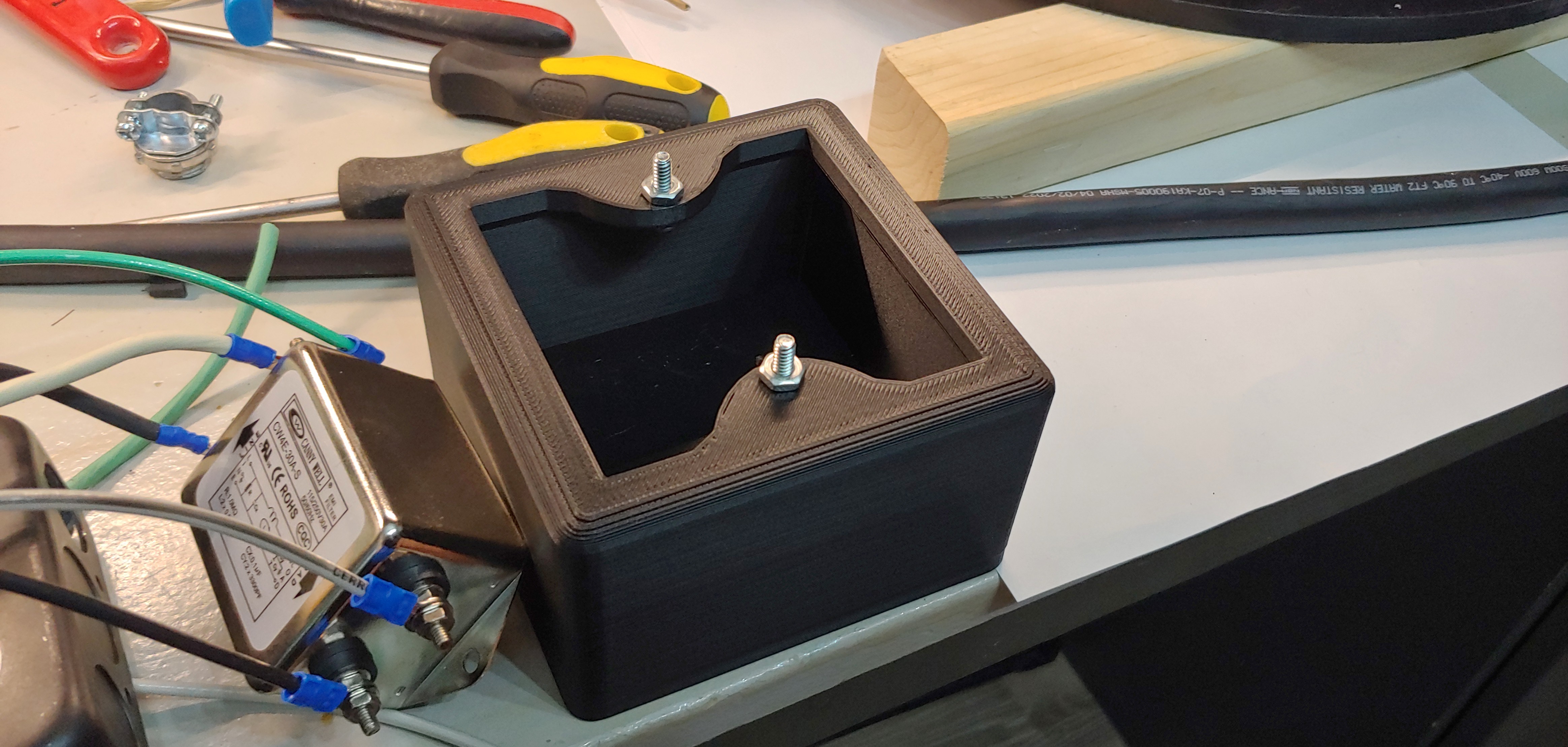
The two boxes marry together with a couple nuts and bolts, which I conventiently used for the grounding lug.
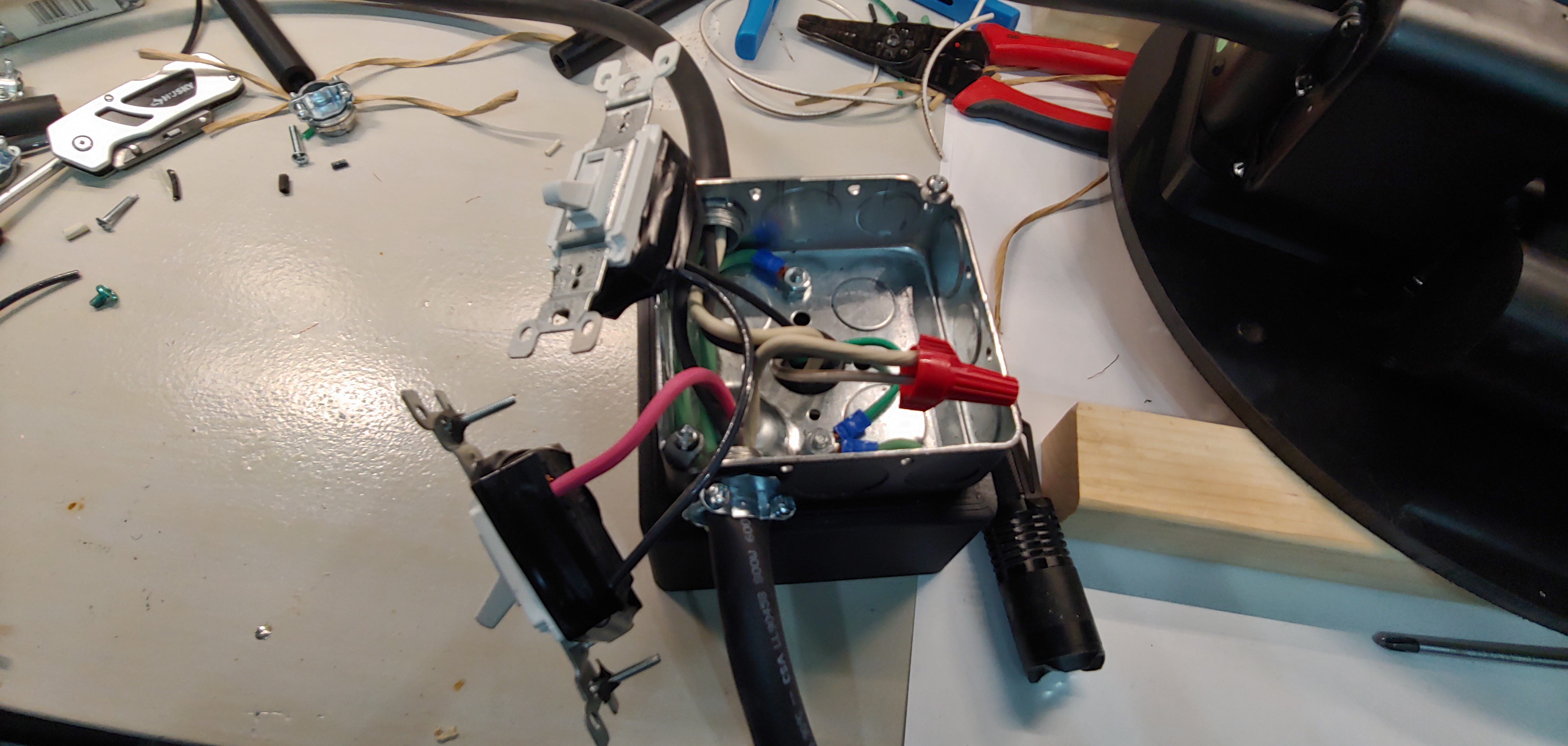
After getting everything wired up, I gave it a quick test to make sure the motor runs and transformers power up without any internal arcing or other abnormal behavior. Everything started right up with no issues. I believe the next step in this process is to figure out the MMC layout and get them soldered together.
Discussions
Become a Hackaday.io Member
Create an account to leave a comment. Already have an account? Log In.