Close
0%
0%

NeoPixel Theremin

Blinking RGB LEDs with 555s and a handful of 74-series logic (take 2)

Similar projects worth following
79 views
0 followers
The goal of this project is to display colorful patterns on a strip of WS2812 or SK6812 RGB LEDs (aka NeoPixels) without the help of an MCU.

A while ago I built the NeoPixel Punk Console, a circuit for controlling NeoPixel RGB LEDs with just 555 timers and a handful of 74-series logic chips. That project did achieve its goal, but the light patterns were very blinky, mainly restricted to primary colors and hard to control.

The NeoPixel Theremin seeks to offer a smoother visual experience, while staying true to the "No MCU" premise.

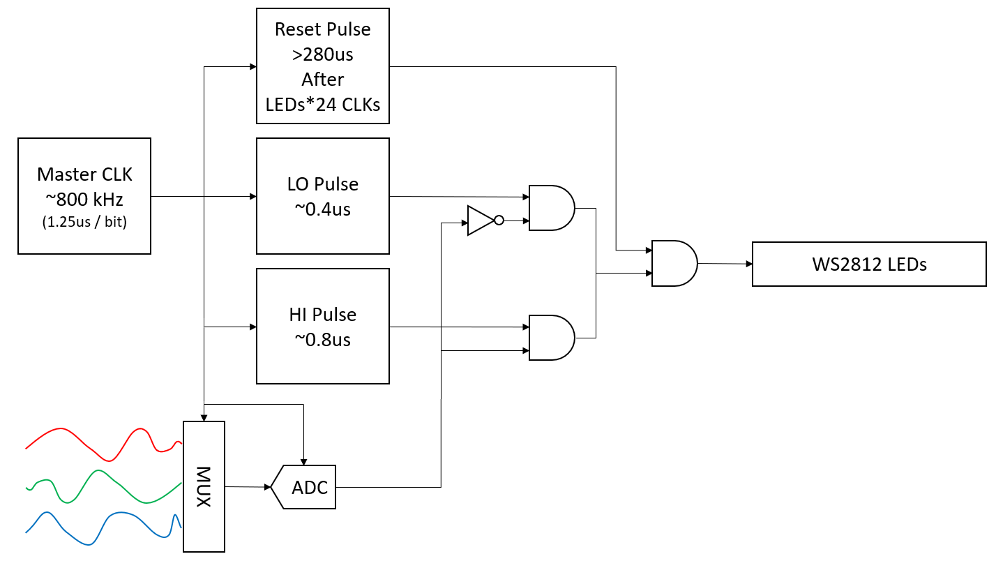
The main issue with the NeoPixel Punk Console is, that its circuit is generating data bits without regard for the RGB data structure the LED string is expecting. To solve that, we will need:

  1. a MUX that switches between 3 analog signals for R, G and B
  2. an ADC that translates the analog signal to digital bits
  3. some logic to keep the above in lockstep with the stream of pulses sent to the LED string

Reusing the 555-based LED driver logic, the new system diagram looks like this:
.. work in progress

  • Integrating the ADC

    Adrian Studer01/23/2023 at 07:12 0 comments

    In the previous project log I settled on a MUX, an ADC with 8-bit parallel output, and a shift register. Something like this:

    For the ADC I've selected the ADC1175 by Texas Instruments, an 8-bit, 20 MSPS ADC with parallel output. It's available in a prototyping-friendly, 0.65 mm pitch, 24-pin TSSOP package and costs less than $4 in singles.

    For the parallel-to-serial shift register I will go with a 74x165, for example the SN74HC165. HC because that's the family I already use in the original NeoPixel Punk Console. The important feature is that this shift-register loads the parallel data asynchronously, i.e. the first bit is available at the output without an extra clock-cycle, which simplifies things down the line.

    For the MUX, I picked the 4052, a dual 4:1 analog switch. For example the CD74HC4052 to stick with 74HC series chips. We will only use one of the two channels, but these are cheap and widely available.

    I will also need a few counters to control the MUX and operate the shift register. No specific selection for those yet. I may be able to just use some logic based off the existing LED bit counter.

    The basic plan is as follows:

    1. Pulse ADC clock to capture sample
    2. Load shift register
    3. Clock out 8 bits to LED string
    4. Switch MUX to next color
    5. Repeat until end of LED string is reached
    6. Reset all counters and restart

    One problem is, that the sample of the ADC is only showing up at the output after 3 clock cycles. So it would take three rounds of the above before the bits of the first sample come out of the shift register. With an LED string, this would mean that the first LED is dark or undefined.

    A workaround is to switch the MUX at the beginning of a color and trigger the ADC with the bit-clock. That way the sample pipeline is already filled with the new color by the time the next load of the shift register occurs. Hard to explain in words, but hopefully clearer with the diagram below.

    After a lot of fiddling (and further tweaking while I wrote this log), here's the timing diagram I came up with:

    Colorization and bit numbering in the diagram reflect the order in which NeoPixels expect RGB data, which is 8 bits each, MSB first, for green, red and blue.

    RST_PULSE, /RST_PULSE, CLK, LED_CNT and LED_FF are signals that already exist in the NeoPixel Punk Console circuit.

    CLK is the master clock at which bits are sent to the LED string, running at about 700 kHz. LED_CNT is the counter for the bits in the LED string. Here it counts up to 12288 for 512 RGB LEDs, but it could be any multiple of 24. When the counter reaches the end of the string, it returns to 0 and triggers the RST_PULSE which resets the whole system. LED_FF is a flip-flop that holds the value of the bit currently sent to the LED string. LED_CNT and LED_FF are clocked by the positive edge of CLK.

    Working backwards from the flip-flop, output SR_Q of the shift register must be valid on the positive edge of CLK. That means the shift register, which shifts on positive clock edges, needs to be clocked before the flip-flop. To achieve this, I created /CLK which is the inverted CLK, except during RST_PULSE when /CLK stays low. As CLK is low for a few 100 ns after reset, /CLK starts with a positive edge before the first positive edge of CLK.

    Next we need to load the shift-register with the output of the ADC at the start of each 8-bit cycle. The shift register is loaded when SR_LD (SH/LD or SH/PL pin in datasheets) is low. As the load operation is asynchronous, bit 7 (MSB) will immediately show up at output SR_Q. To load the flip-flop with the correct bit, SR_Q must update between the negative and the following positive edge of CLK. With that, the SR_LD pulse should happen when SR_CNT is 0 and /CLK is 1.

    SR_CNT counts from zero to seven, clocked by CLK. Instead of a dedicated counter, the lowest three bits of LED_CNT can be used.

    Next up is the ADC. It captures new samples shortly (3ns) after a negative clock edge, and data output is valid on the...

    Read more »

  • Finding an ADC

    Adrian Studer01/16/2023 at 06:25 0 comments

    First I will need an 8-bit ADC, with a simple enough interface to be driven without an MCU. Ideally, I'd like to have a pulse to initiate the analog-to-digital conversion, and then 8 pulses to clock out the result - preferably MSB first as that's the bit order the LEDs expect.

    Most ADCs that I've found use a SPI-like protocol like this:

    CS transitions low to initiate a conversion, then a few dummy bits need to be clocked out before the MSB of the result shows up. So for each 8-bit color value we'd need to pause sending data pulses to the NeoPixel for a few clock cycles.

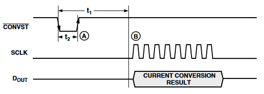
    Another, less common serial protocol looks like this: (AD7823)

    While not requiring extra clock pulses, this ADC does require a pause for the conversion to complete. This isn't an issue if the pause is much shorter than our clock (~1MHz). Unfortunately the AD7823 requires a 5us pause, and I didn't find any faster ones.

    One approach to avoid pausing the bit stream to the LEDs would be to place the ADC with the signal source and interleave results with the MUX.

    The downside is cost (3x $10 for the AD7823, ouch!), and for the cheaper and more common SPI ADCs the complexity of orchestrating the extra clock cycles.

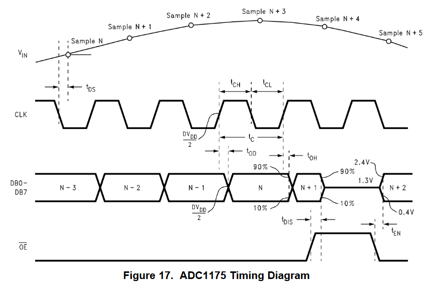
    There are also ADCs with parallel output. The TI ADC1175 looks like a good candidate:

    Similar to the SPI ADCs, the conversion result is only available after 3 extra clock cycles. But after filling the pipeline, a new sample is available with every clock cycle. So worst case, we may have an issue with the first LED on a string.

    A parallel-to-serial shift register will be required to convert the 8-bit data to a serial stream. The logic would be something like this:

    1. switch mux
    2. start ADC conversion
    3. parallel load shift register (with sample N-3)
    4. clock out 8 bits
    5. repeat

    This seems doable with very little extra logic.

View all 2 project logs

Enjoy this project?

Share

Discussions

Similar Projects

Does this project spark your interest?

Become a member to follow this project and never miss any updates