 CYUL
CYULPCBs were received from the fabrication house and they work!
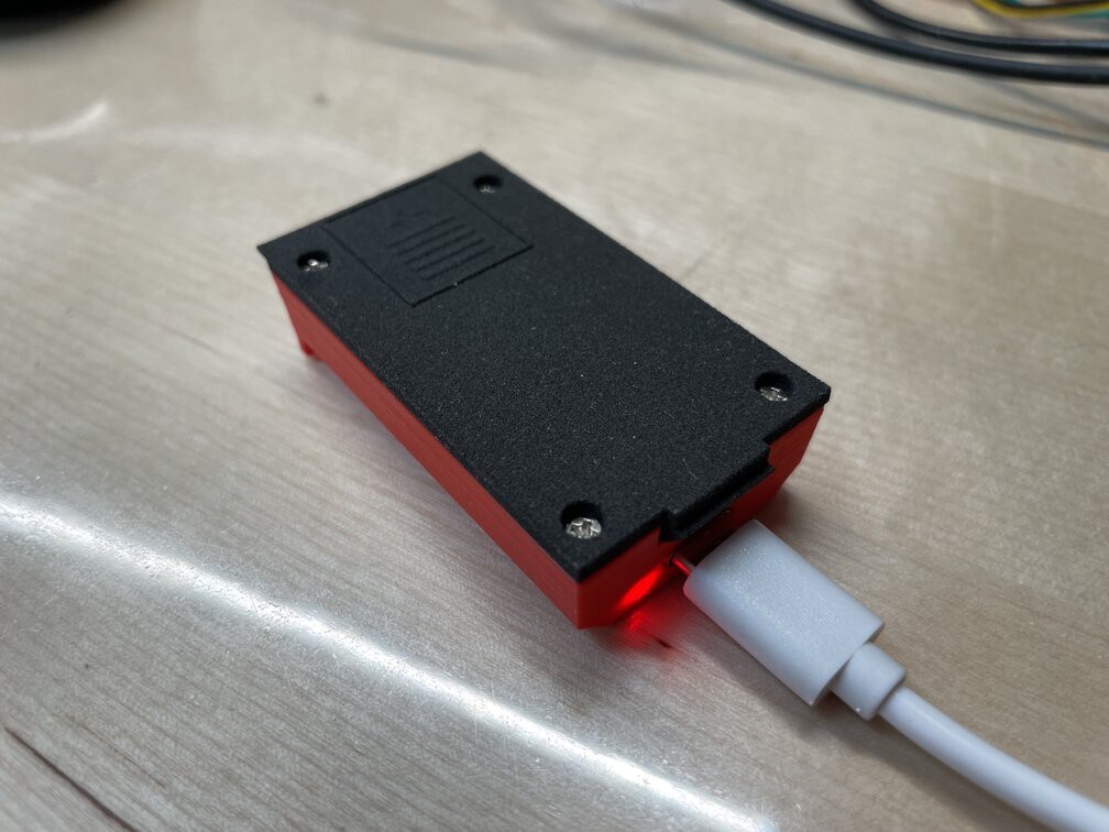
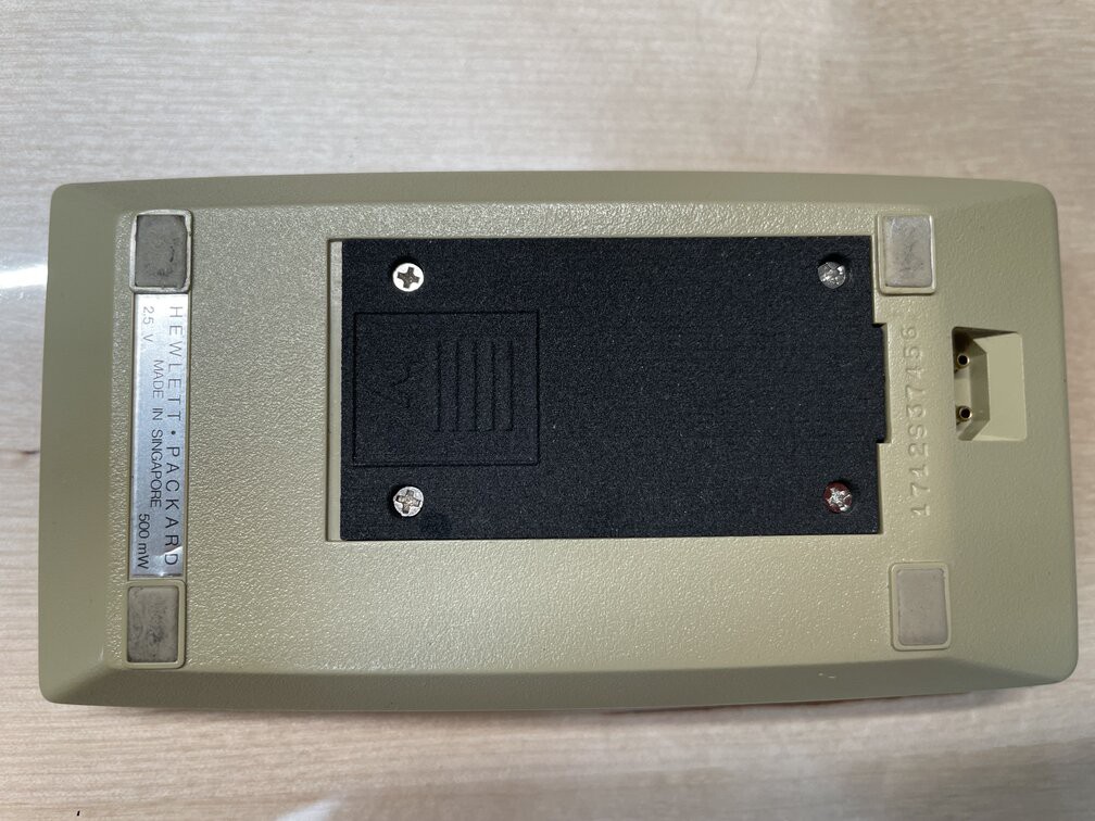
Here is a photo of the battery pack being charged inside a temporary housing that I 3D printed using my trusty Ender Pro while waiting for the laser sintered parts that I ordered, then another one with the pack in place (it is exactly as difficult to remove from the calculator as the original), then a picture of a happy calculator.
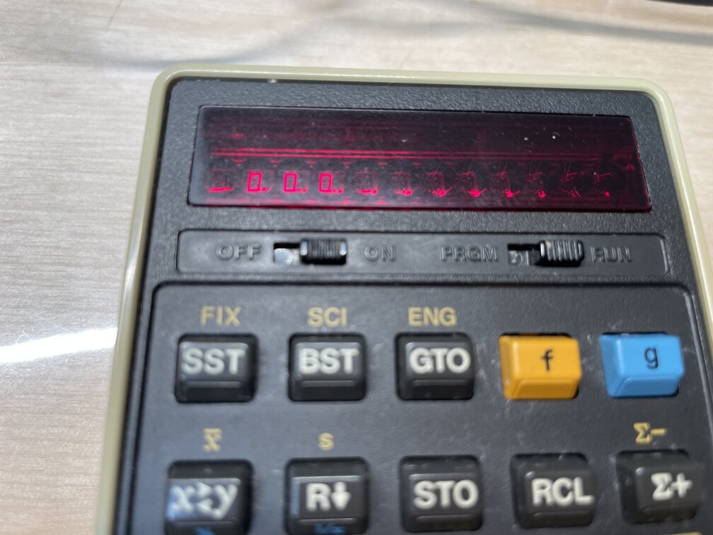
LED displays take such a weird hue in digital photos, what's this about?
Also, why is it so difficult to find beige/cream/ivory/bone white PLA anywhere?
The next step is to integrate a Qi receiver in there. I looked around and there doesn't seem to be any hobbyist friendly solution. I am currently looking at Texas Instruments (oh, the irony!) BQ51050B chip. The datasheet is very unhelpful. Wireless looks hard! Thankfully that (expensive!!!) chip is available in a 20 pin VQFN package. Whereas I was soldering most of this by hand, soldering this much smaller package of a chip seems like a challenge. It should be feasible with patience, some solder paste and a hot plate (literally a hot plate: I plan to use our ceramic stove). I would use a 20mm coil.
If anyone has hints on how to calculate C1 and C2, or a working design I could reference, please hit me up.
Discussions
Become a Hackaday.io Member
Create an account to leave a comment. Already have an account? Log In.