 Savo
SavoWith one board complete as a proof-of-concept, it was time to progress to the final stages.
Tuning the Code
Since the capacitance of the boards belly pads was different to the jumper wire I used for prototyping I had to adjust the threshold values a bit to match. This took a few trials but nothing too bad, just about 20 minutes all in all.
Similarly I had to decide how often to have the raccoon check the pad for changes in capacitance. This needed me to weigh the responsiveness of the system to how long they'd last on their batteries. In the end I found that having them check every other second was generally responsive enough. Using some rather simplified math with generous assumptions, the estimated life was found.
Where P was the portion of time that the ATtiny85 was active (checking capacitance. I didn't bother to include the time the eyes are on since I assume that this will be a very marginal occurrence, perhaps no more than five times a day so it can be neglected. By checking once every second, the P would be about 0.01 since the check would taken 10ms itself on average. The idle current was treated as 4.5 uA, the active current 7.2 mA.
Doing the math this gives a rough average current of 76.5 uA, which using the reference 340mAh for a CR2032 cell would give about 185 days on a single battery. Less than the year I wanted, so I halved the check frequency which would almost double that lifespan!
Mass Assembly
I assembled nine boards of the ten I ordered (one was lost to my ATtiny harvesting when I had issues with power).
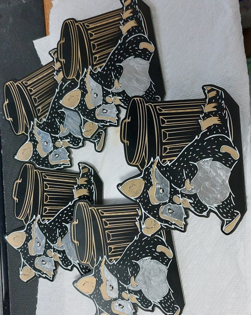
A group of raccoons is called a nursery or a gaze. I however feel that gang is more fitting for the little thieves.
All but one of these boards have been handed out as gifts by now.
Making a Stand
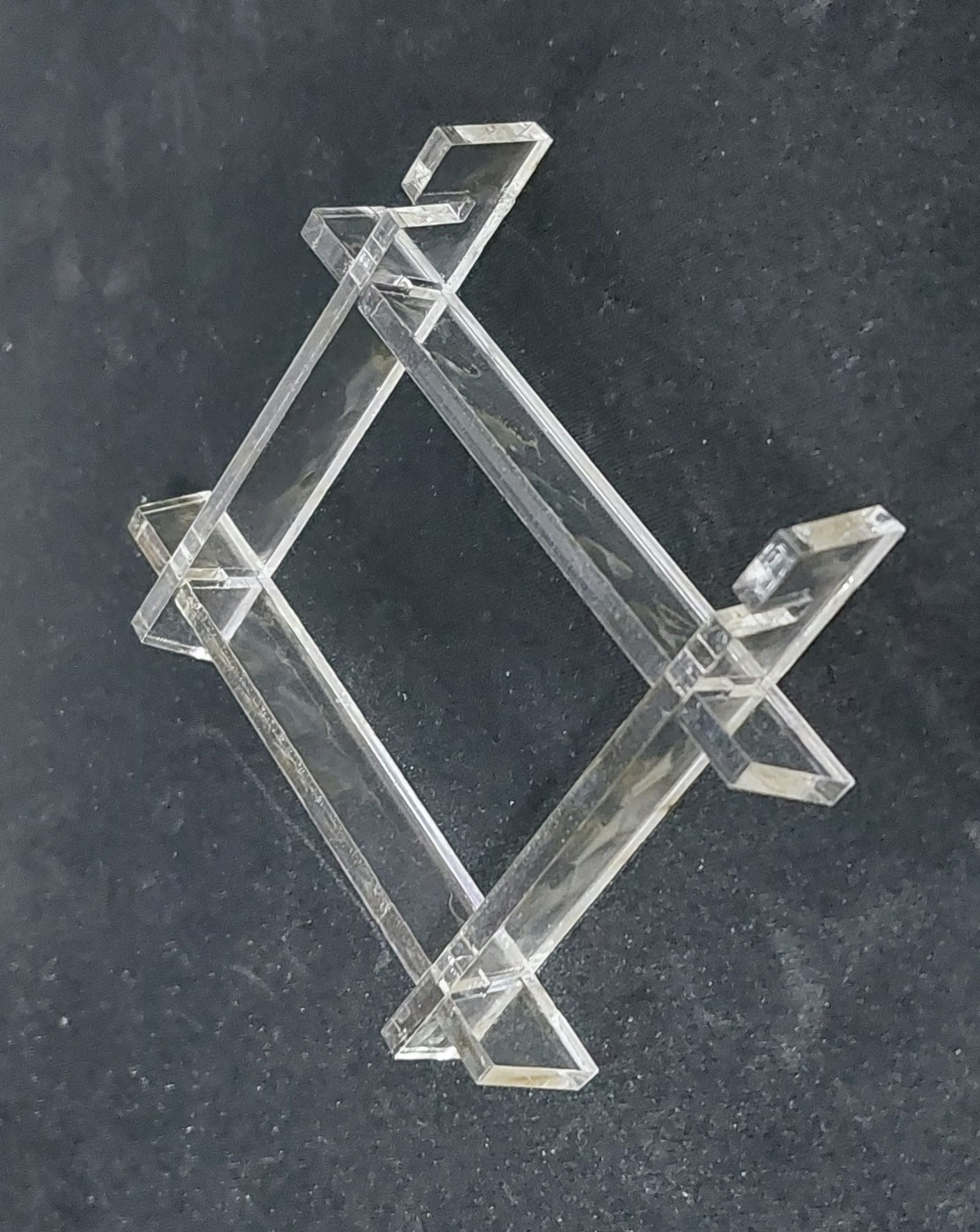
In addition to the board I wanted to make a small and simple stand to hold the boards upright for people. I wanted to make it small so I could send it easier, while also being easy to manufacture and later assemble. I decided on laser cutting some parts from 1/8" (3.1mm) thick plastic, since I have a few friends that can arrange this for me.
My final design was a set of four interlocking pieces that the board simply slides into. Two parts hold up the board, and the other two are used to hold them 50mm apart. This was my first time using FreeCAD so it took me a bit longer than I would have if I was using SolidWorks or Inventor, but I think the results are nice anyways. Might need to brush up on how to make nice drawings though.
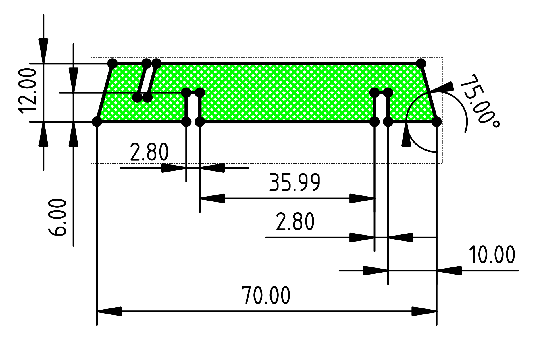
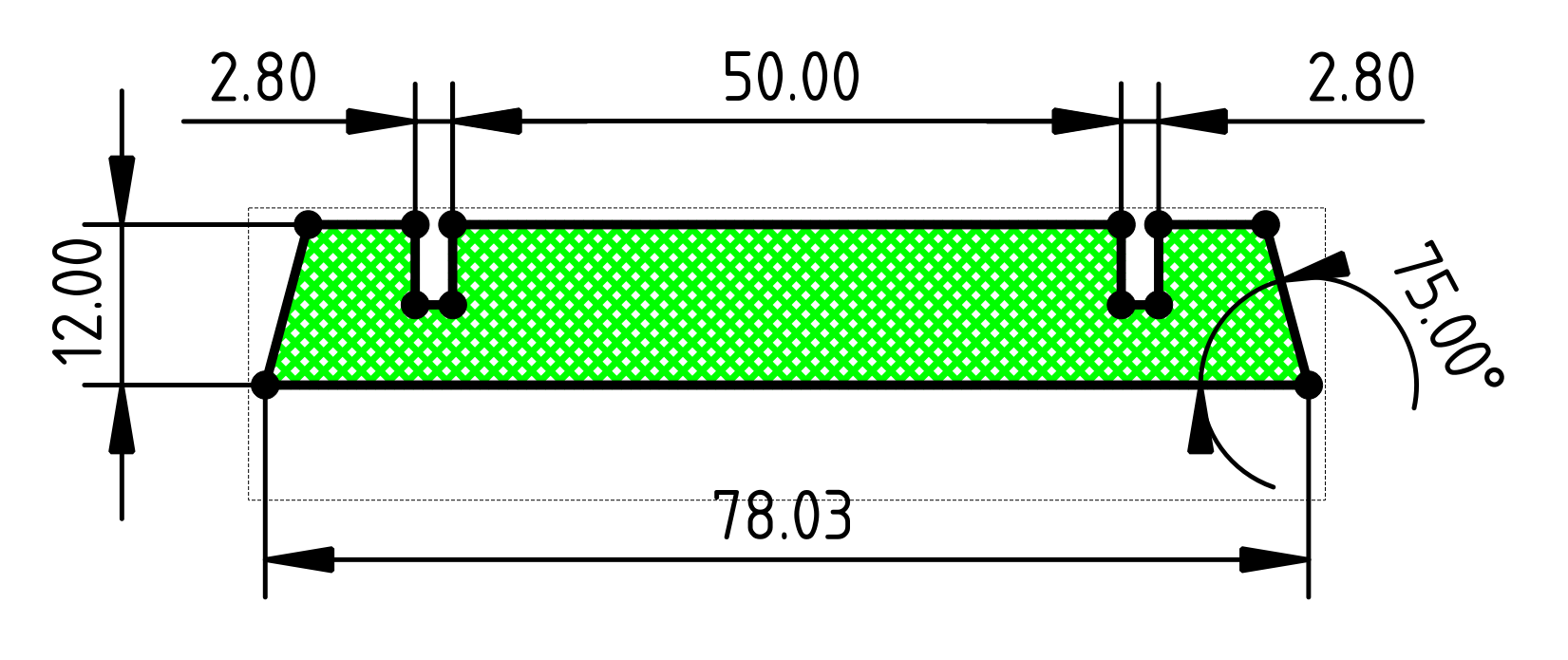
I made one round of prototype parts to see if the width of the slots was just right. They were a bit loose so I narrowed them and the results were just right as shown below. (These final dimensions are reflected in the drawings above.)
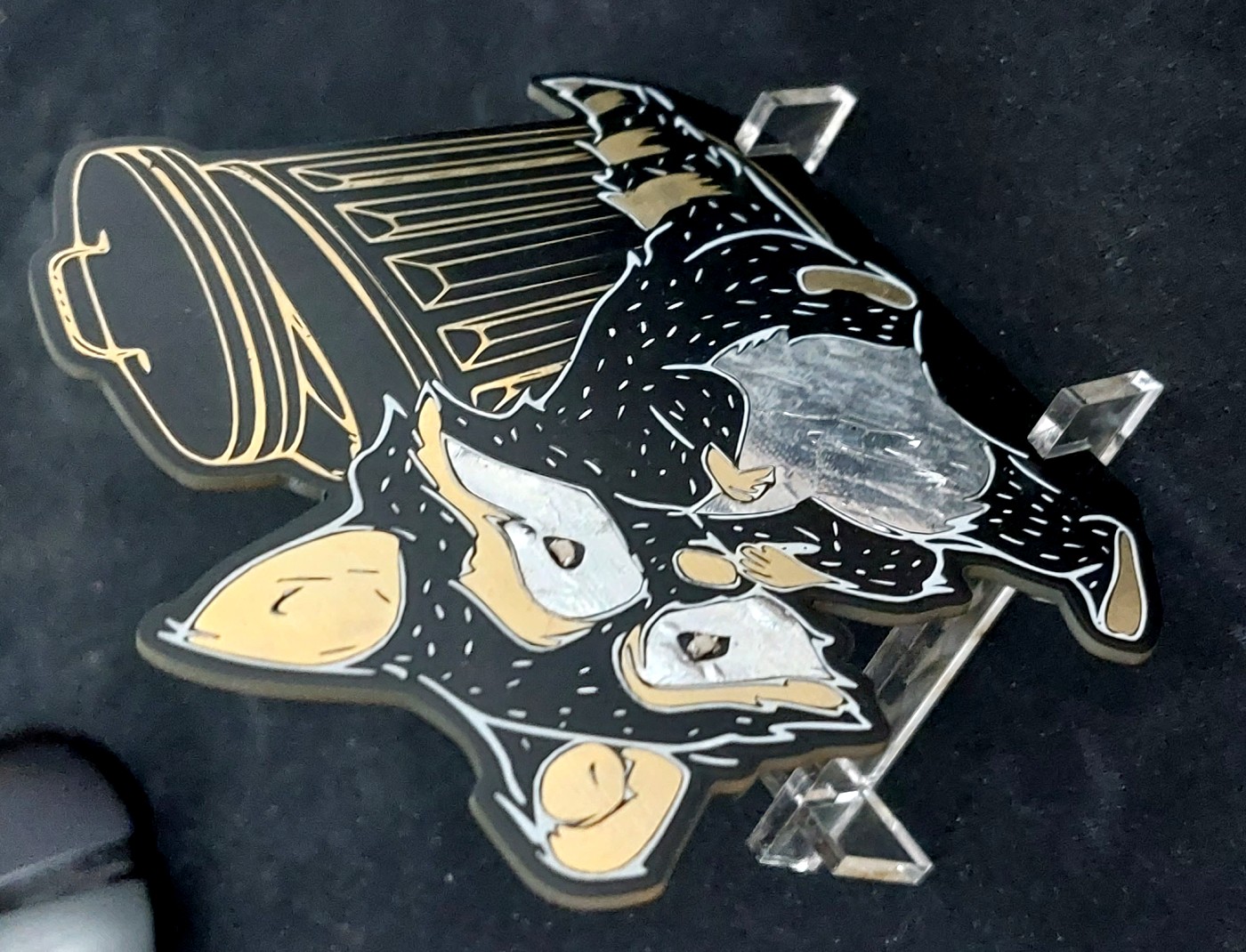
Final Result
With the stands designed, I just needed to have my friends cut more pieces for me and I was able to start handing them out!
Discussions
Become a Hackaday.io Member
Create an account to leave a comment. Already have an account? Log In.