 Ruslan
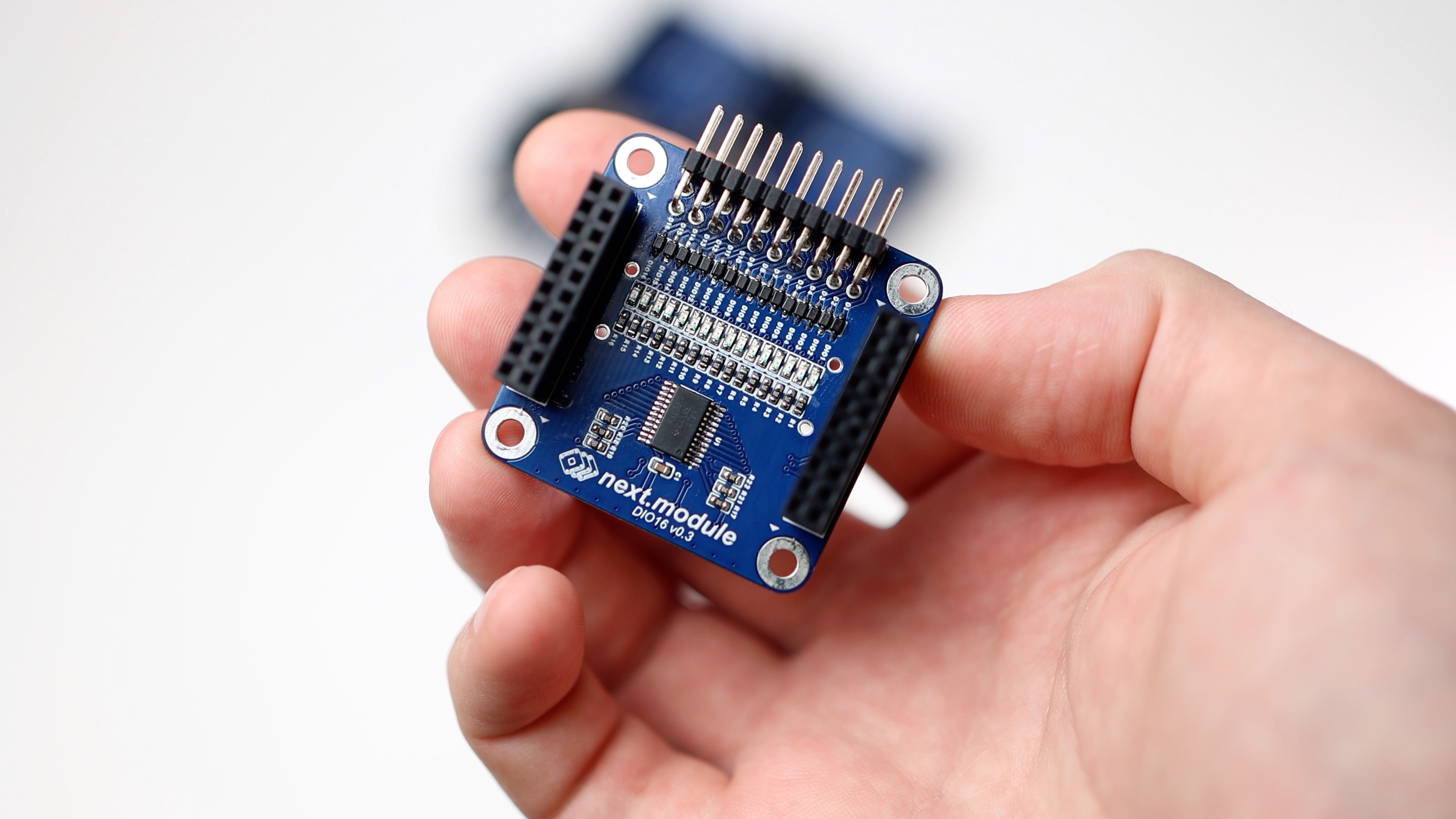
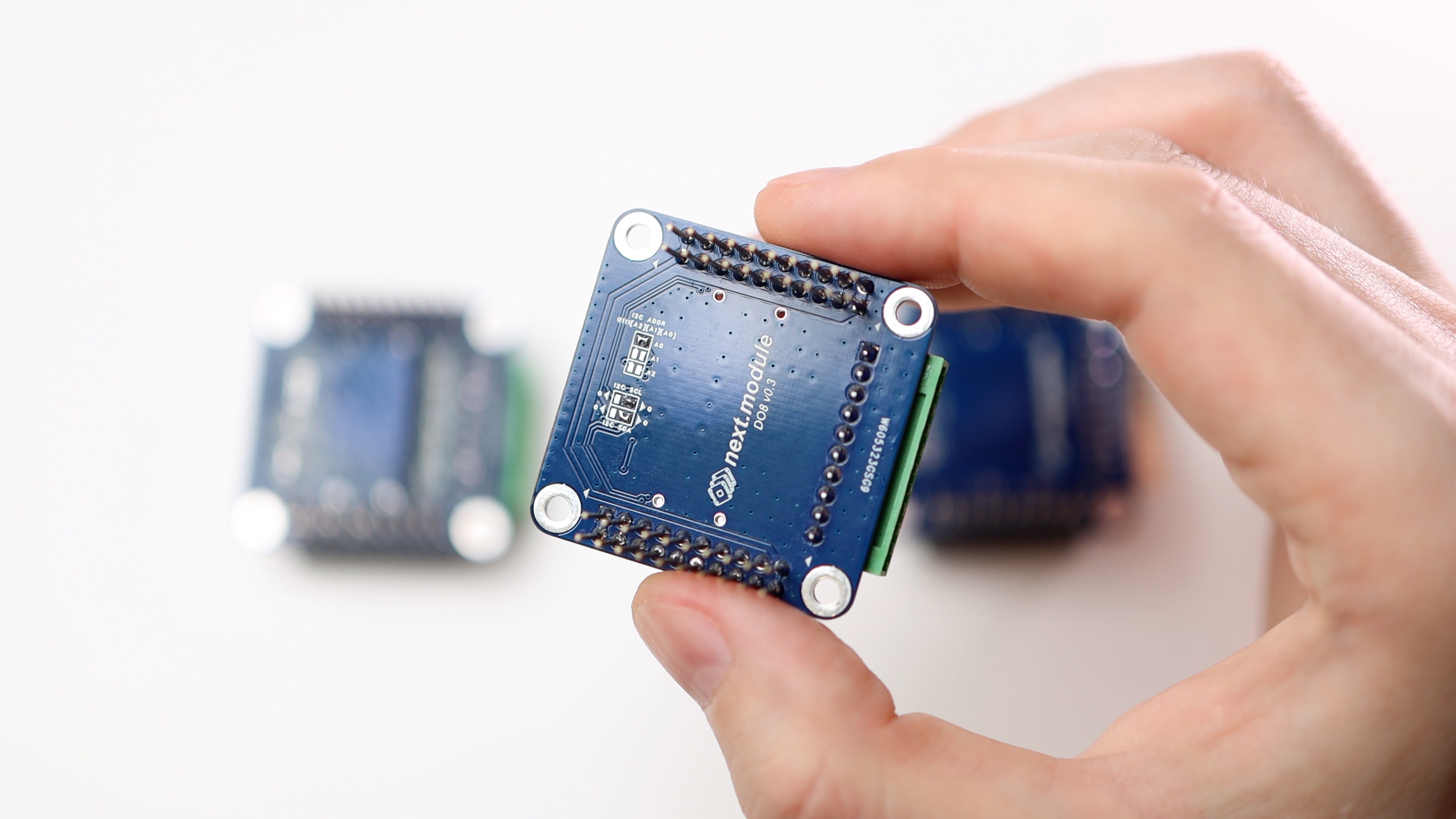
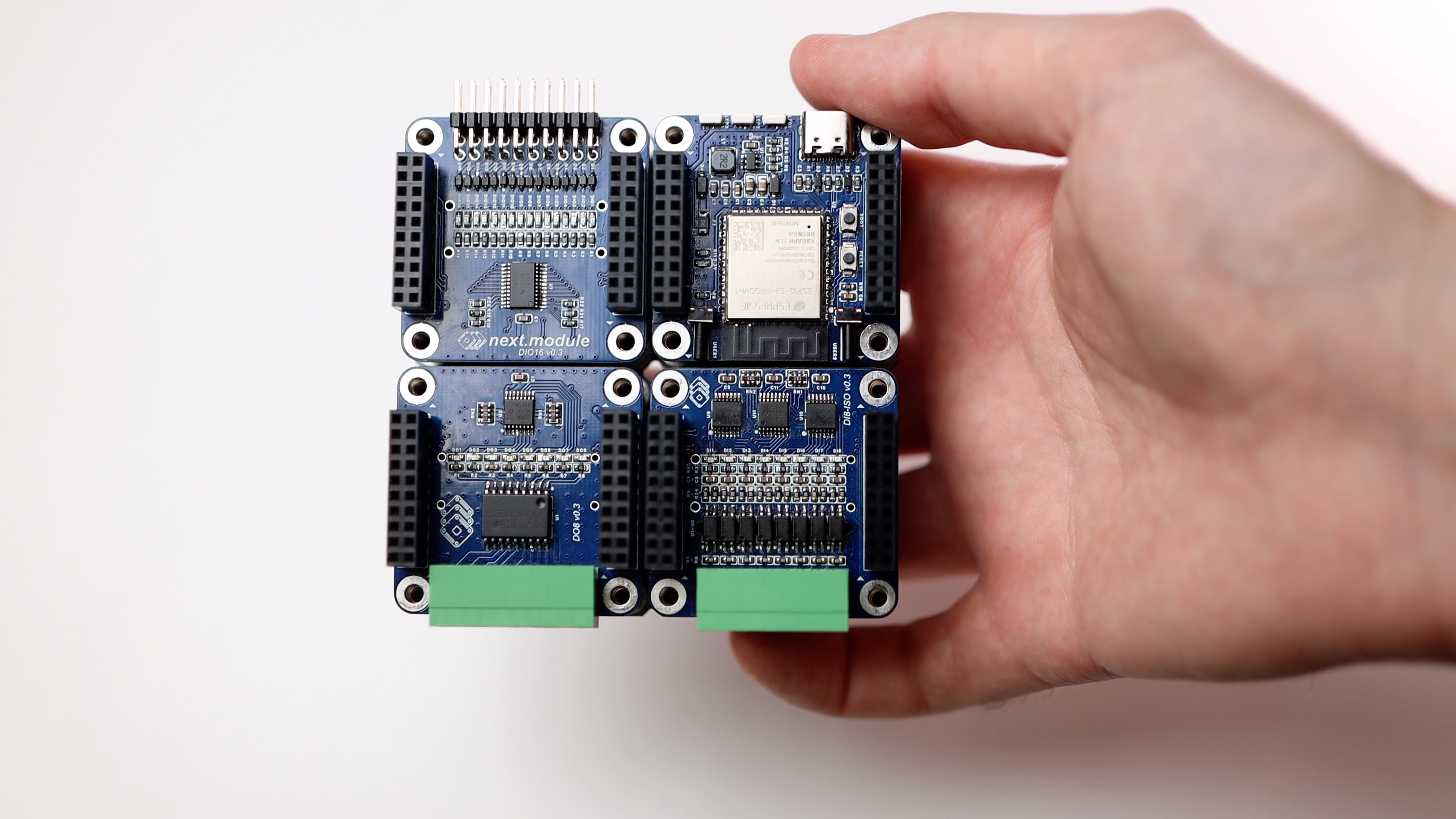
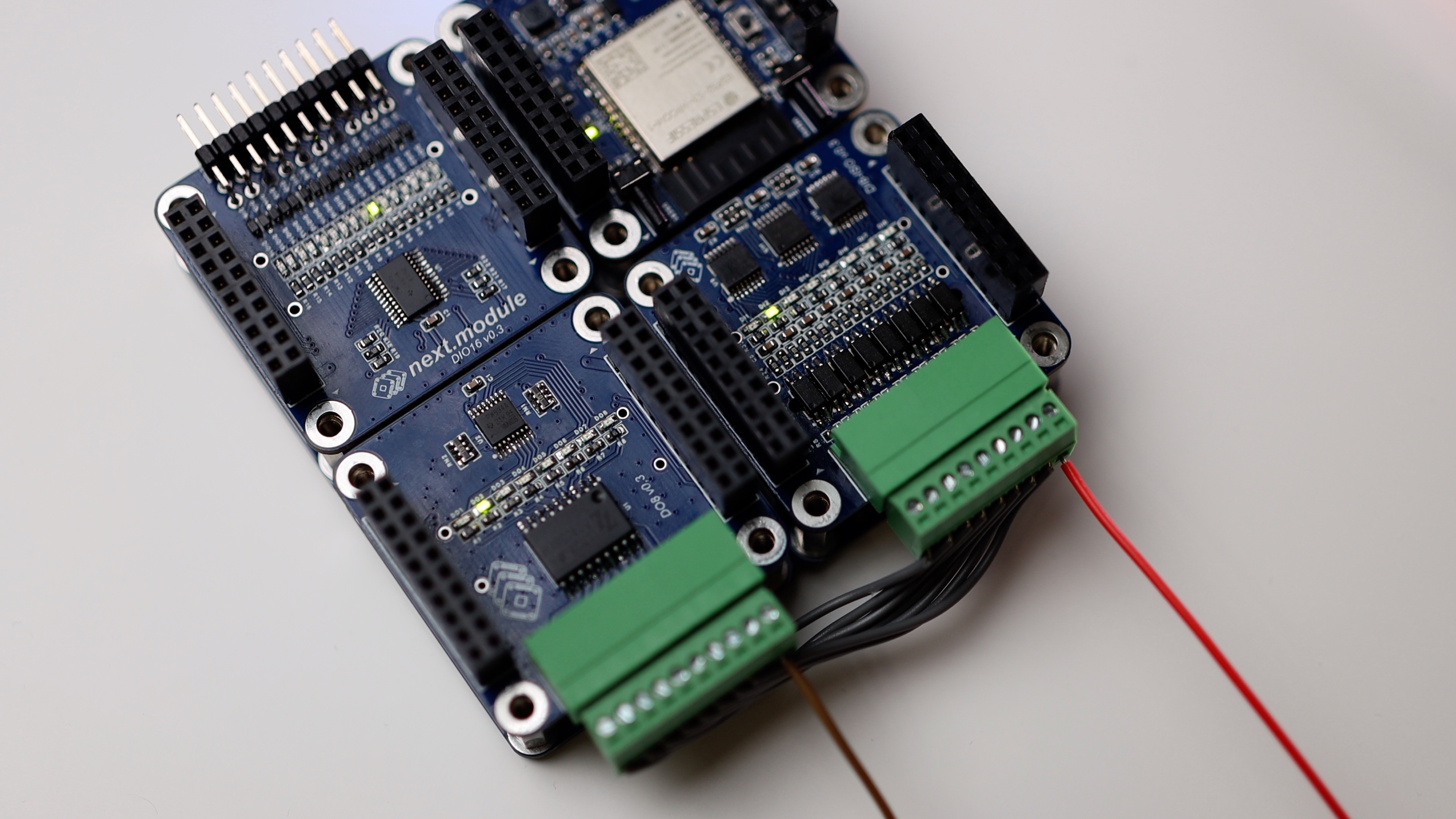
The modules DI8-ISO (8 inputs), DO8 (8 outputs) and DIO16 (16 GPIOs) have been tested and they all work fine.
However, there are a few things that need to be fixed:
🟠 In DI8-ISO, I need to increase the resistance to limit the current through the optocouplers. Currently, it is 2K, and when a 24V input is applied, we get a current of 11 mA, resulting in heat dissipation of 250 mW on a resistor that is designed for only 100 mW. To trigger the input, it is sufficient to pass 1 mA through the optocoupler.
🟠 In DO8, I need to add a short circuit protection. General, group, or individual (I haven't decided yet).


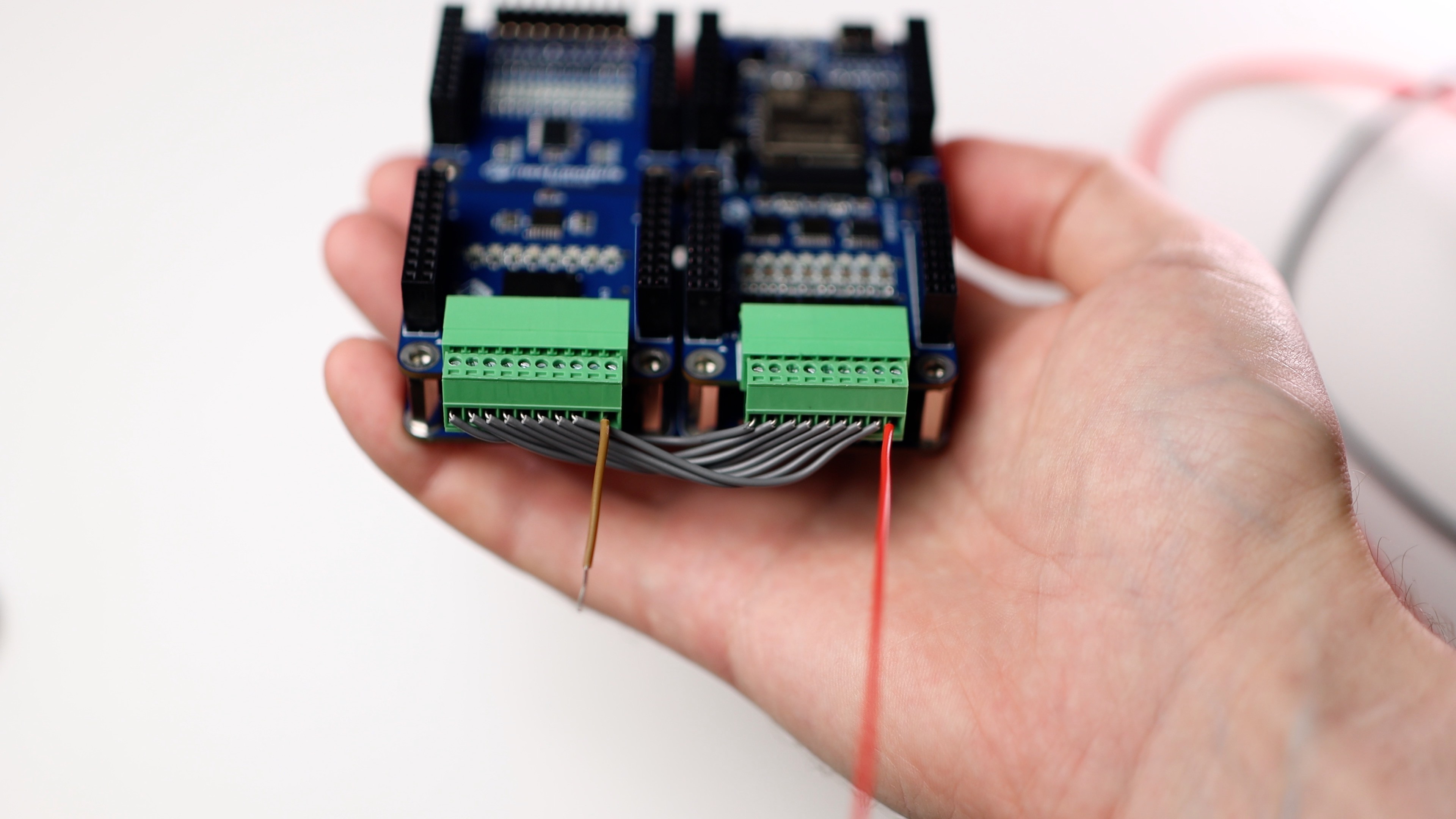
The inputs can be connected to the outputs directly. This requires a power supply to provide current through the optocouplers.
#nextmodule #digitalinputs #digitaloutputs #devboard #plc #module #esp32 #tca9534 #tca9535
Discussions
Become a Hackaday.io Member
Create an account to leave a comment. Already have an account? Log In.