 Ruslan
The idea is to redirect light from the module’s onboard LEDs to the front/back surface above the connector.
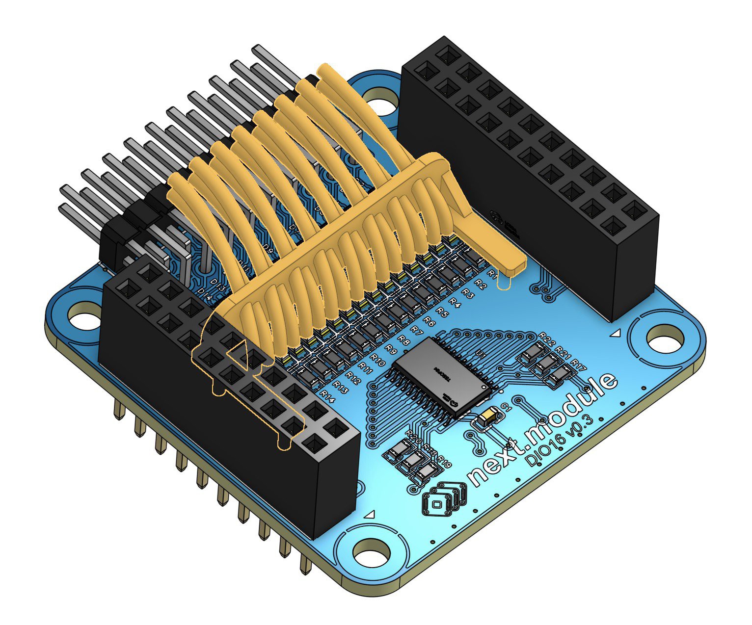
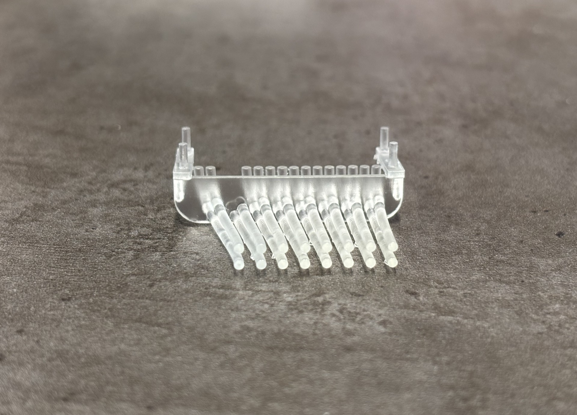
The first prototype focused on the most complex configuration: the light guide for the DIO16 board. It consists of 16 separate tubes diverging from a single row of 16 LEDs to form two rows of indicator points above the connector. On this board, the four rightmost connector pins are ground, so the light guides must be curved to align the indicators with the corresponding signal pins.
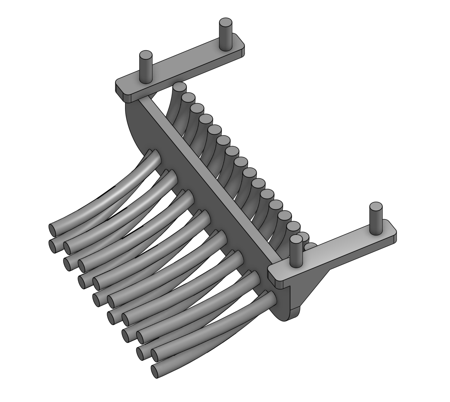
The model was designed for simplicity. The PCB 3D model was exported from EasyEDA and imported into OnShape. Splines were drawn from each LED to its target point above the connector, and 1.5 mm diameter tubes were extruded along these curves. The tubes are connected by a 1 mm thick vertical wall, which fits into four mounting holes on the PCB for stability.
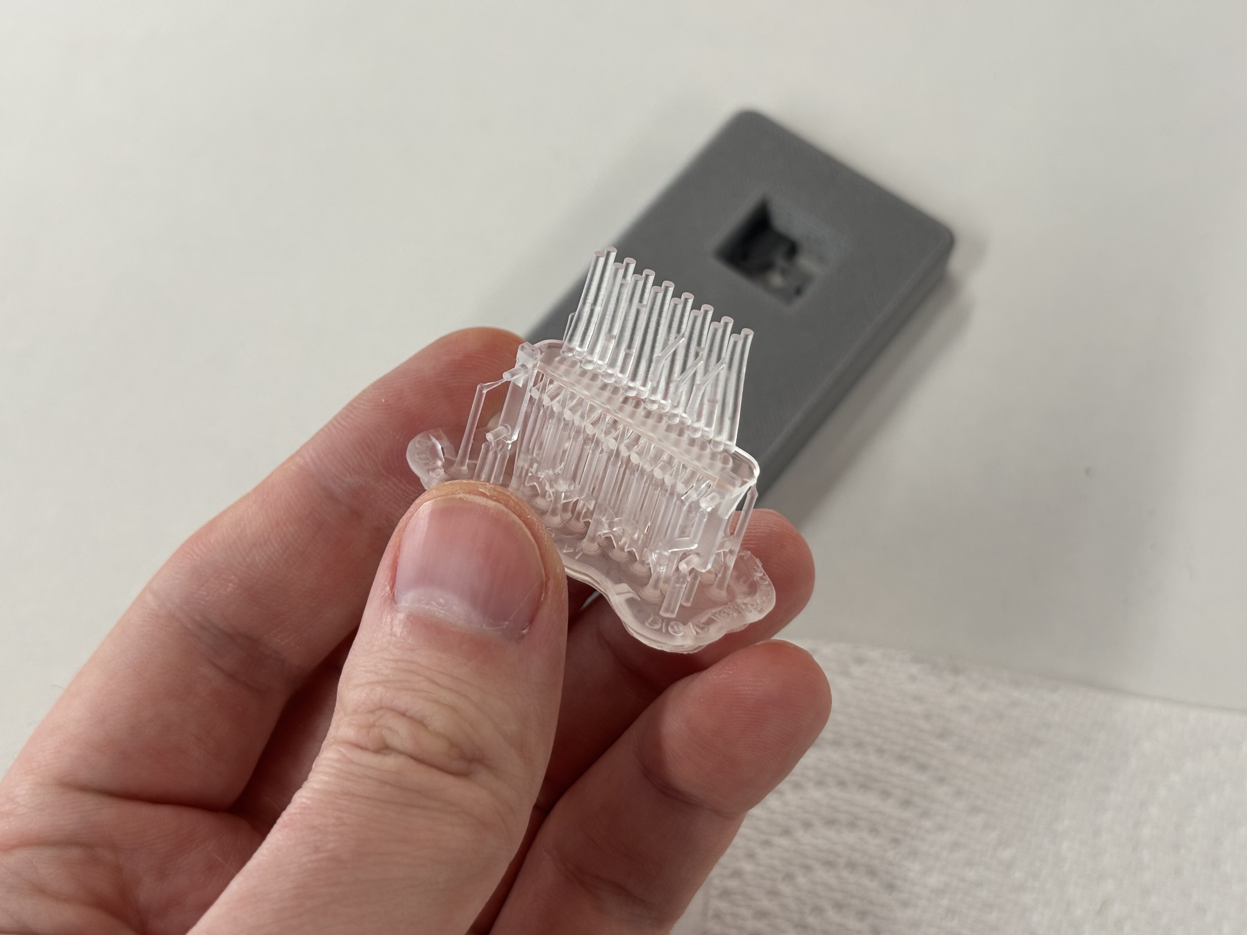
The light guide was printed in Formlabs Clear Resin V4.
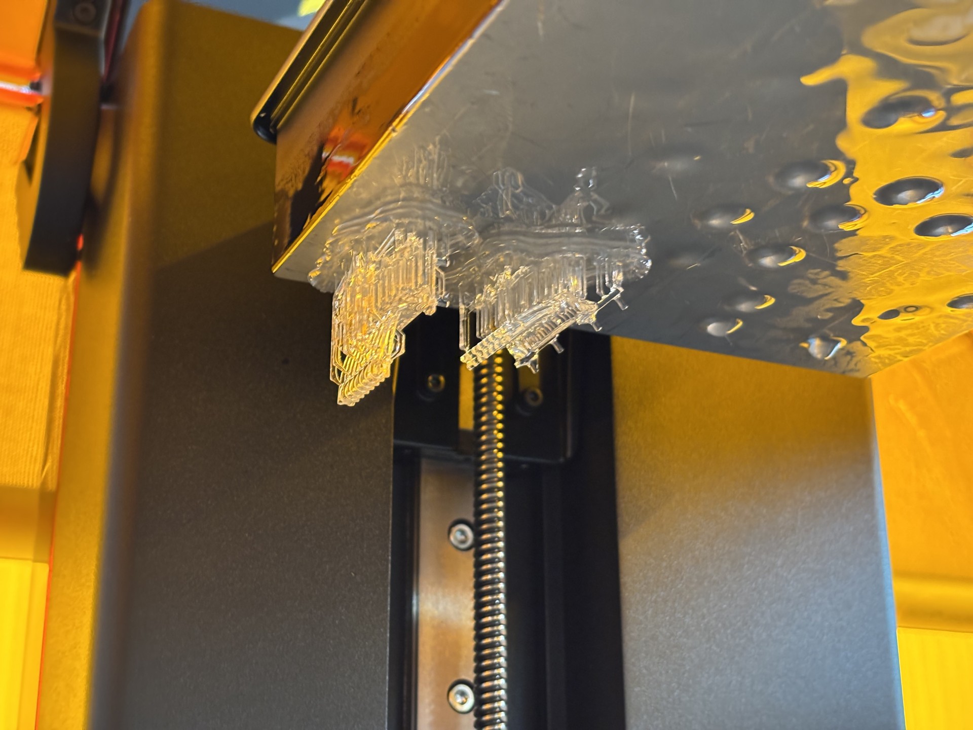

After UV curing, the part became slightly cloudy and yellowed.
During the first print, two tubes were broken while removing supports.
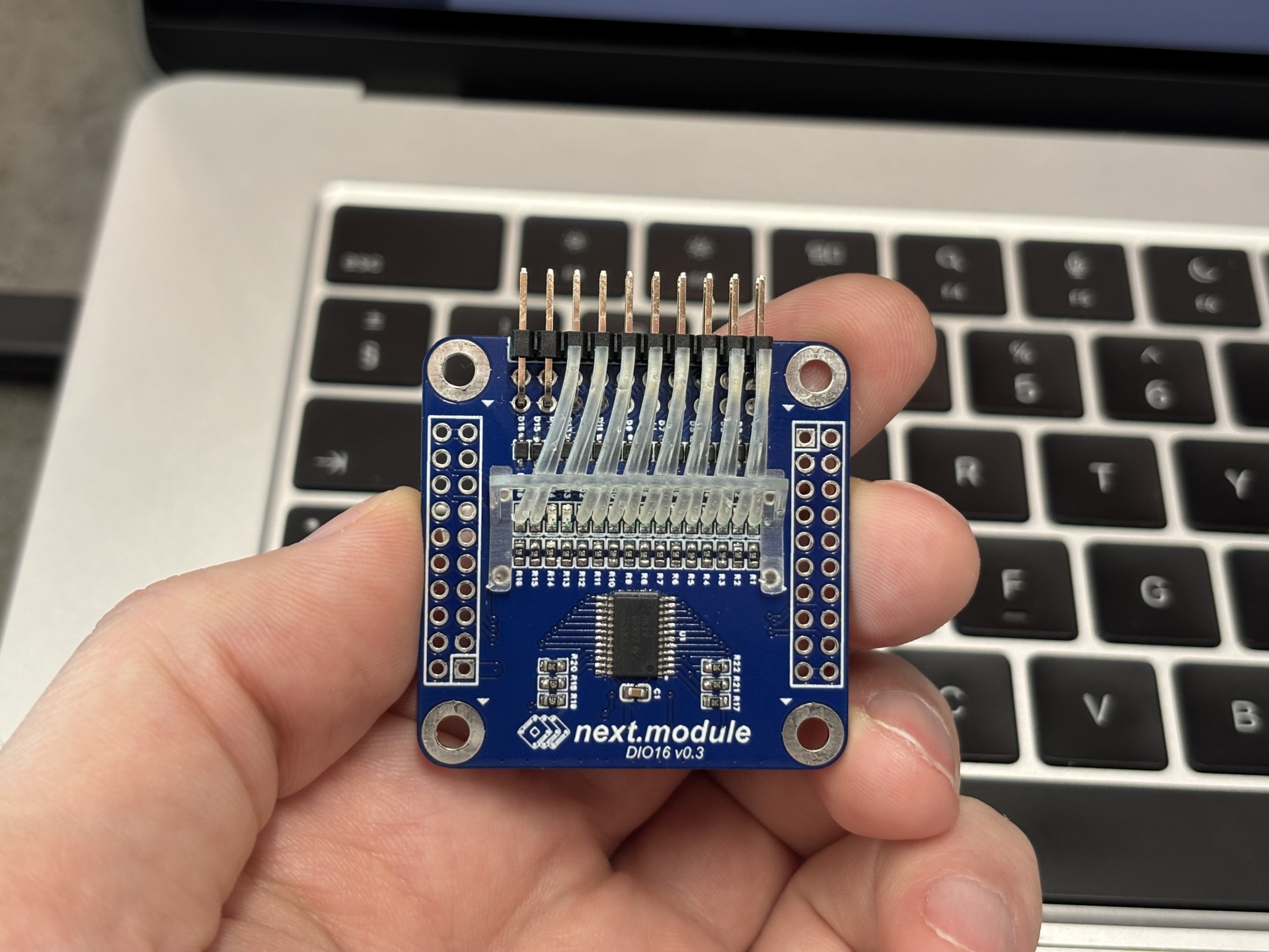
Dimensional accuracy was preserved, and the part positions precisely on the board.

Performance is mixed. Light from adjacent columns is clearly distinguishable, but light from paired LEDs in the same column mixes significantly.
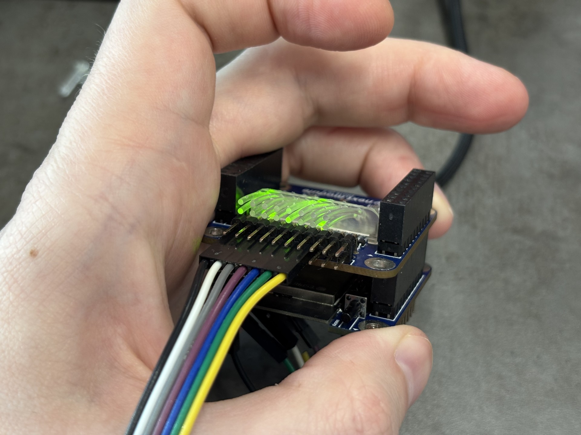
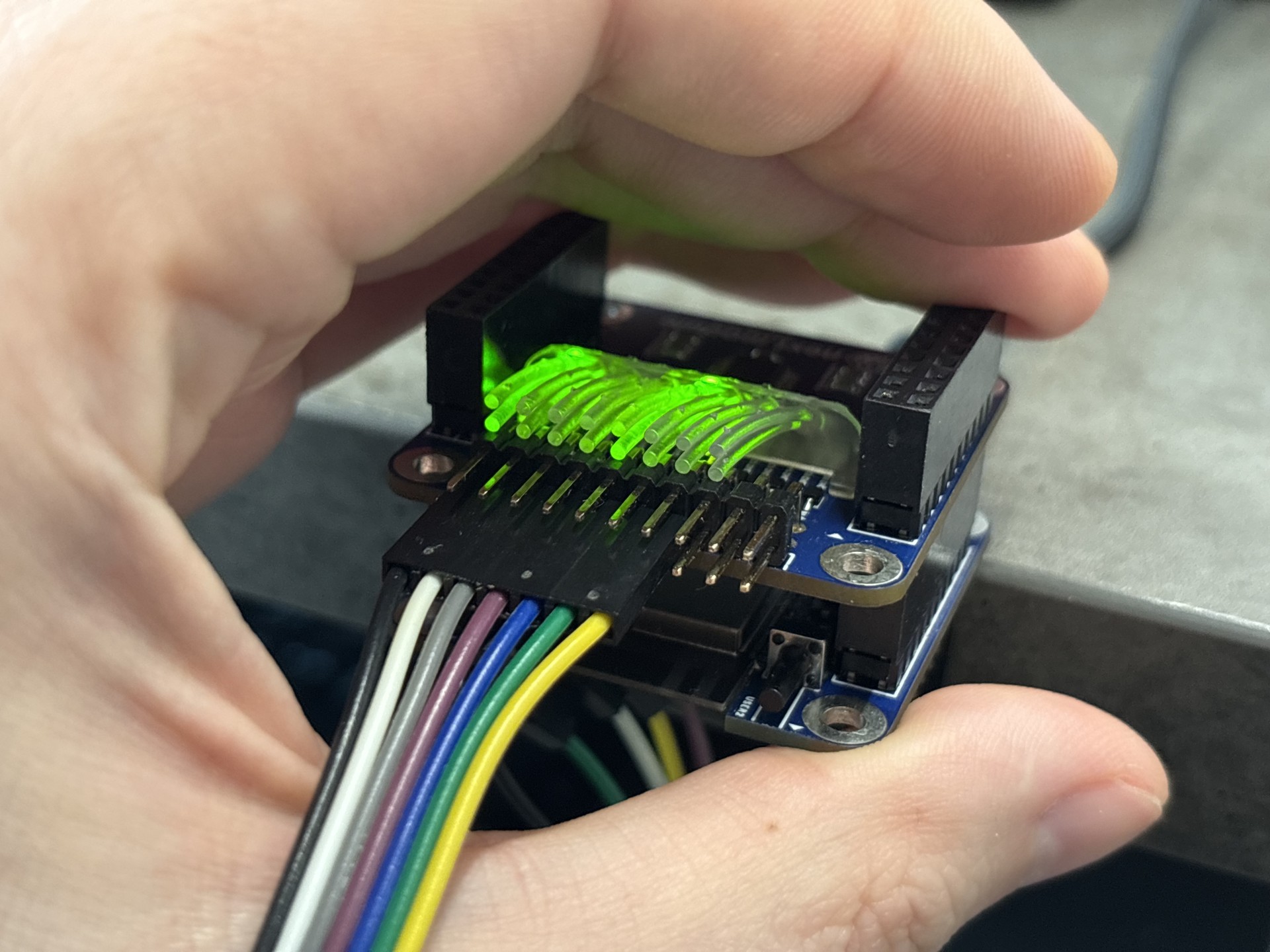
The main cause is the close spacing of the tubes near the connecting wall. Increasing the distance between them and using brighter LEDs could improve visibility.
The material is heat-resistant, so soldering the light guide to the PCB is not possible. Additionally, this complex geometry is only suitable for 3D printing—molding is not feasible. Future development requires simplifying the design, redistributing LEDs on the board, or considering a separate indicator PCB.
Discussions
Become a Hackaday.io Member
Create an account to leave a comment. Already have an account? Log In.