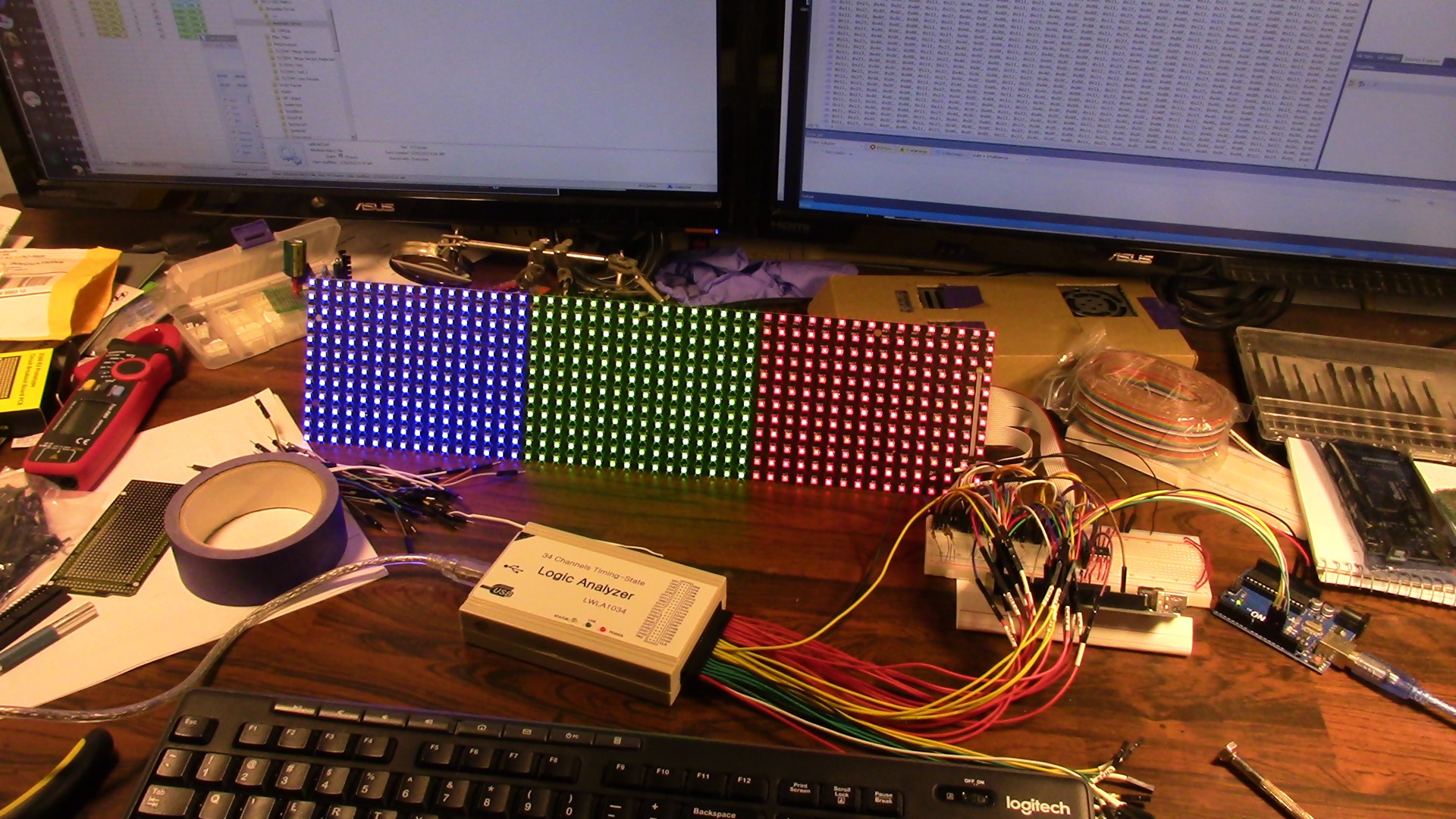
More progress writing the driver software. TL;DR: Arduino IDE is pants, rewrote it in AVR Assembly.
First let's talk about the strategy to run four panels from a single atMega2560 MCU. I decided that to minimize processing, and thus maximize speed, I should do some pre-processing of the image data and pack the bits in a way that's efficient to output. To whit, I gathered all of the IO lines from four panels and packed them into the available outputs on the Arduino Mega 2560:

This scheme was alluded to in the previous log with the sample source code. a standard 24-bit bitmap has one byte for R,G and B values in groups for each pixel. Preprocessing the image data separates the RGB values, and then repacks the bits such that the first byte of the output contains the first bit of the R, G and B streams. Each byte of output is equated to one port per the above image.
Further, the order of the pixels is accounted for: The pixels are sampled starting at row 12, column 16, and across the row to column 1. On the LED panel this maps to (assuming Bank 1):
L400, L399 [...] L385. L208, L207 [...] L193, L16, L17 [...] L1
The data stream for the entire 48x48 display is therefore 5 bytes wide (using 5 ports on the MCU) by 48*8 long; a total of 1920 bytes. Per row. When we account for there being four rows, that's 7680 bytes to fully define the 48x48 pixel image. Luckily the atMega2560 has 8192 bytes of SRAM, meaning we can stuff one full frame of image data into the faster SRAM space with a few hundred bytes left over for things like stack space. Yay!
Now for those paying attention, you might recall that the drivers use 36 bits per pixel - 12 each per color - but we're only sending 24? We do this by padding extra bits, as zeros, to the beginning of the data. This reduces the maximum brightness without messing with the original image data, which is perfectly fine because these things are CRAZY bright at full power and run quite hot to boot, so this reduction makes it much more appropriate for use as, say, a wall display.

The preprocessor is written in VisualBasic6 because that's how I roll. The output is a *.asm file that simply gets included at compile time, and one of the first things the CPU does is copy it from program memory into SRAM.
Enough rambling, let's get to some code! Everything is written for AtmelStudio 7, which is now known as Microchip Studio. I've not used the new IDE but I'm sure it's fine.
The main.asm and imgData.asm files are available for download through this project. There is a copious amount of comments explaining what each and every instruction is doing, which is essentially identical to the sample code in the Part 3 project log.
While I wait for the bits I need to clean up this nightmare of wiring (which causes TONS of problems with signal noise, BTW...) the next step is to find a way to mount these panels to a frame along with all the gubbins.
Discussions
Become a Hackaday.io Member
Create an account to leave a comment. Already have an account? Log In.