After getting some optical parts from an estate giveaway, I thought it was worth putting them together to kick off this project.
I scrapped my initial design from a few weeks ago, and decided to start with getting the viewfinder optics functional. Most of the Nikon F2 viewfinder is not needed, but it’s interesting to see what was done. The light meter is contained inside of the Nikon F2 viewfinder, with two CdS photoresistors plugged towards the eye piece of the viewfinder. The repair manual shows some simple schematics, but it lacking on some of the connections. Regardless, from what I understand, it seems that the two different photoresistors are biased for different light levels, and then compared between the values to move the analog needle. Will look into this further in the future, as doing something similar with two digital light level sensors would be interesting. Two pins were used for powering the circuit, but some work will have to be done to figure out how to get digital communication through the unit without drilling more holes, etc. It would be nice to not have an external connector, but it may be needed to get all the data lines needed. Otherwise, a one-wire bus would be useful.
One other interesting note is the prism has what appears to be a sticker, to cover up where the light meter and AI-S F stop was shown in the viewfinder. A mirror currently sits over the area, but it may be better to use that mounting hardware along with a display to show various settings. Future work again.
Back to the design part: there are 3 pins on the Nikon F2 viewfinders, which was the more difficult part to measure to have something functional. The viewfinder sits on top of the focusing screen, which is just a fresnel lens. The one I’m using is a Nikon F2 T type focusing screen, and there are many different versions. This was the only one I had that uses a split lens in the center for easier focusing, but any others could be used.
There are some spring contacts on the bottom of the viewfinder that sit ontop of the focusing screen. I’m not entirely sure how compressed the springs are supposed to be, but it looks like it doesn’t need to do much other than hold the focus screen in place so it doesn’t rattle. I have a Nikon F3 that I compared the distances to, and it appears like the spring contacts aren’t compressed much, and the image looks slightly out of focus when holding the focus screen up to the viewfinder.
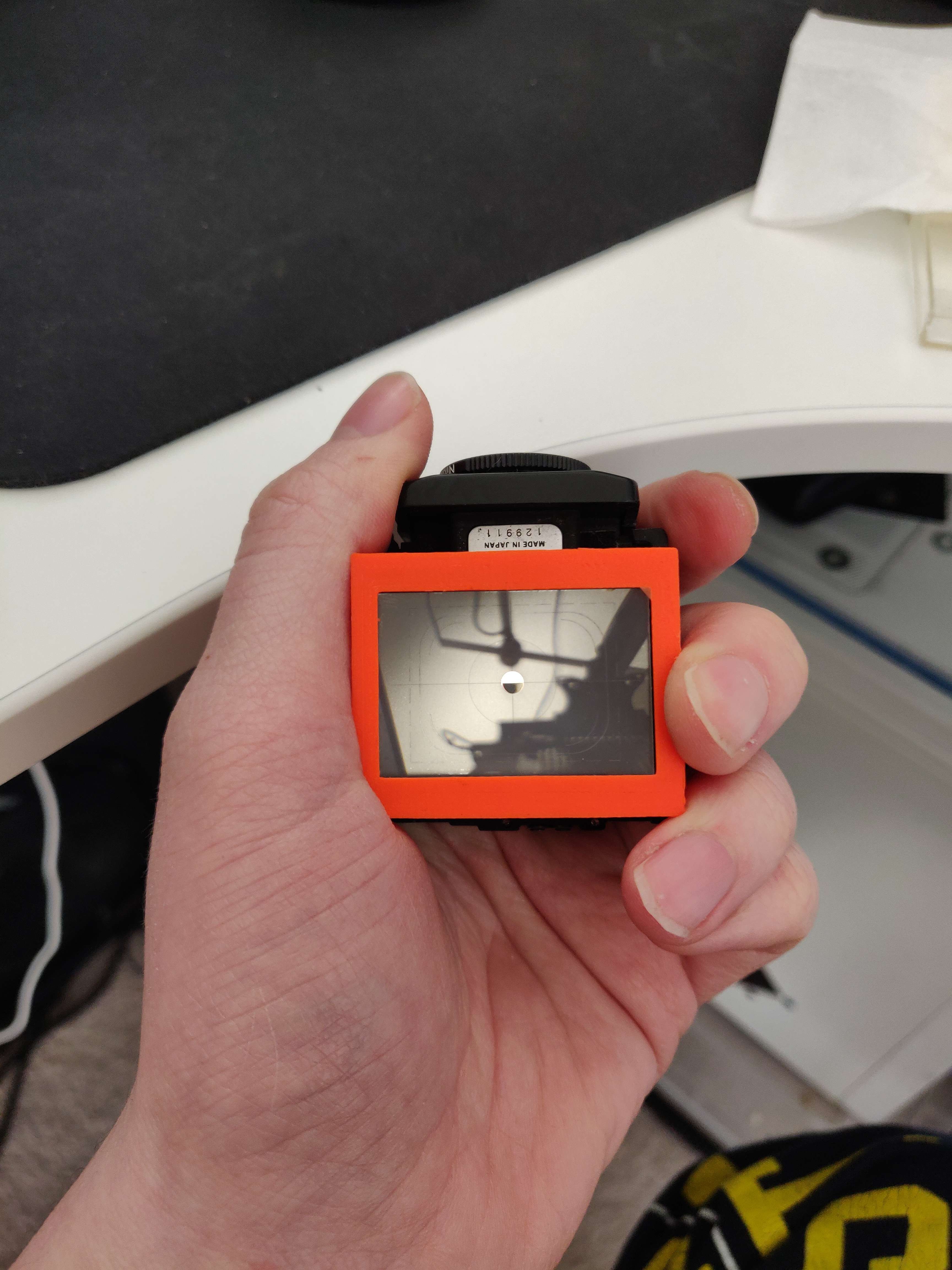
The resulting 3D printed mount looks as follows

Looking through the focus screen in reverse looks about the same as the Nikon F3, so I feel it’s safe to say that this is a success
 Dylan
Dylan
Discussions
Become a Hackaday.io Member
Create an account to leave a comment. Already have an account? Log In.