 Jon
JonOverview
The Smart Plant was designed to be flashed with the ESPHome firmware, however it can be directly programmed through Arduino or ESP-IDF. And since the code is yours, so it's the data you gather, stream it to your Home Assistant server and automate your irrigation on the plant's demand!
Want to get one?

In any case, all the design files are available on my Github, and I have prepared an extended documentation page for any user willing to know more about the project
Specifications:
- Microcontroller: ESP32-S2-MINI-1-N4R2 with 4 MB in-package flash and 2MB PSRAM
- Firmware compatible:
- ESPHome, highly recommendable for its native integration into Home Assistant
- Arduino
- ESP-IDF
- Sensors:
- Soil moisture: Capacitive probe built-in
- Light: VEML7700-TR digital sensor
- Air Temperature & Humidity: AHT20 digital sensor
- Battery level: MAX17048 digital sensor
- Power:
- 3.7V 1000mAh LiPo battery
- Charging through USB-C or solar panel (5V @500mA)
- Deep-sleep mode consumption: 450-500μA
- Standard mode consumption (10s awake, 1h deep-sleep): ~1mA
- Interface:
- USB-C for charging and programming
- UART port
- 2.4GHz Wifi
- Display: 2.9" black & white e-ink from Waveshare
Version log:
- Version 0: Very early prototypes to serve as proof of concept.
- V0R1: Protoboard with headers to be used as a shield for the TTGO T5 e-ink module
- V0R2: PCB designed to host the same module but with some additional THT components integrated
- Version 1: First designs on black PCBs with a more aesthetically oriented design.
- V1R1: Integrated the ESP32-S module and a photodiode as a light sensor
- V1R2: Corrected previous power module and replaced photodiode with LDR
- Version 2:
- V2R1: Replaced ESP32-S with ESP32-S2, added battery level sensor and digital light sensor.
The story behind
I started this project because I was missing some features on the popular Xiaomi Mi Flora. Those devices, despite being very useful, lack a key point: readability. Every time I wanted to check my plant's health I had to go to their app... With time I learned how to implement them into Home Assistant, receiving the data via Bluetooth on my RPi 4 and plotting the graphs I needed on my custom dashboards...
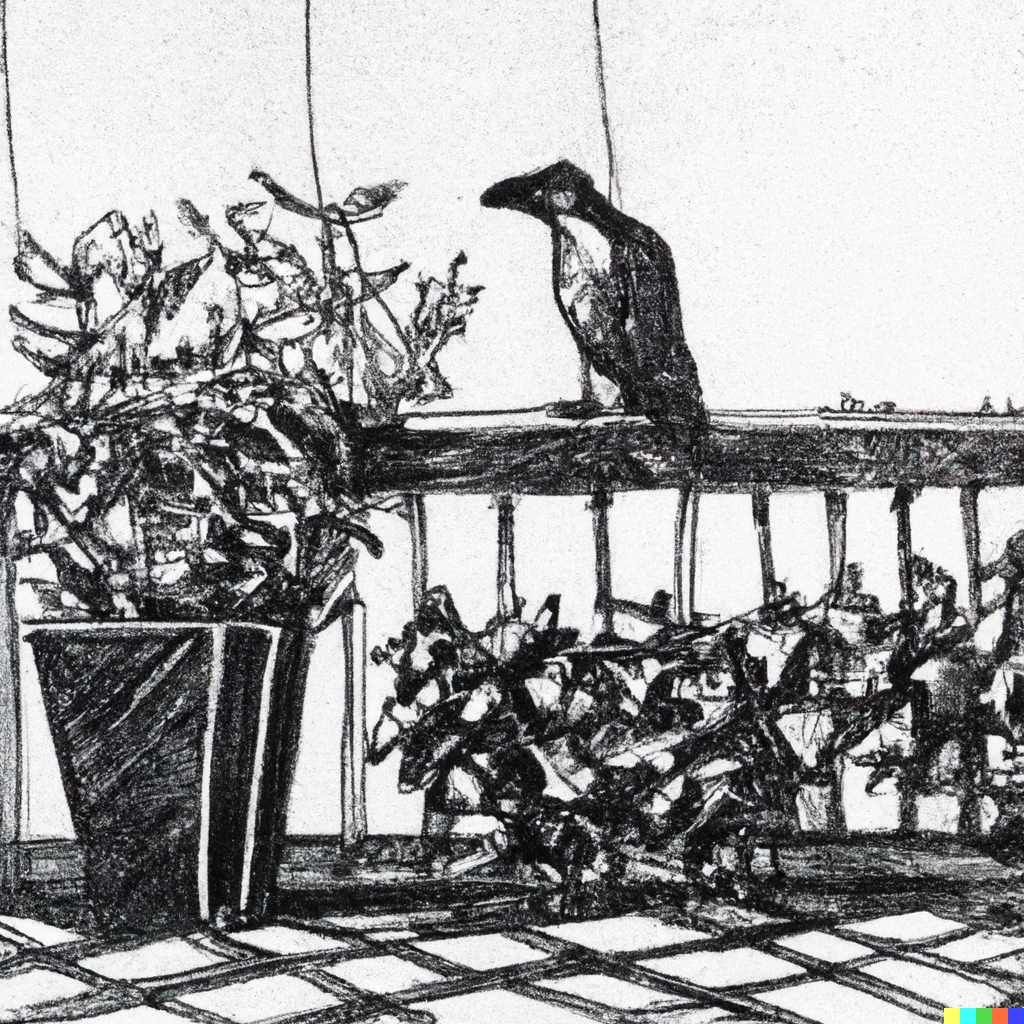
One day, I realized one of my Xiaomi's sensors was missing on the balcony pots. After an inquisitive search party, I found out that one of the black ravens from my neighborhood just decided to add this gadget to his collection of stolen items...
With a pot missing a key instrument for the plant's survival, I decided to come up with an alternative gadget that, not only would keep the features of streaming the data into my Home Assistant setup, but also provide more of a user-oriented readability features.
Daily usage: automations
I chose ESPHome as the main firmware for the Smart Plant, not only because of the direct support for the e-paper panel and the rest of the sensors on board but also because the integration into Home Assistant (HA) is immediate.
Through HA you can flash ESPHome directly on the Smart Plant and start logging the parameters from the first minute. Additionally, you can prepare beautiful dashboards to display the data and set some automations.
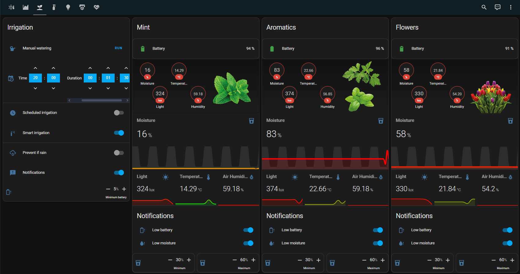
In summer, I have the Smart Plants on my balcony plants (4 different pots). Each of my pots have an individual irrigation pipeline that I control through my other project Smart Garden and the assistance of some automations programmed in HA. The automations do basically:
- At a certain time of the day (20:00), the system checks the moisture level of each of the Smart Plants.
- If the moisture is under a certain level for each specific plant, I send the command to the Smart Garden to open the corresponding solenoid valve.
- Additionally, if the battery level of the Smart Plant is under a certain level ( 5%), I get a notification through the HA app directly on my phone.
For some time I also had a condition set to check forecasted rain, but since the plants are mostly covered, I felt this feature was unnecessary.
In winter, I bring some plants inside, so the automatic irrigation is discarded. Nevertheless, I get a notification if the soil moisture is still under the recommended for each plant so I don't forget watering them manually.
Components
Sensors
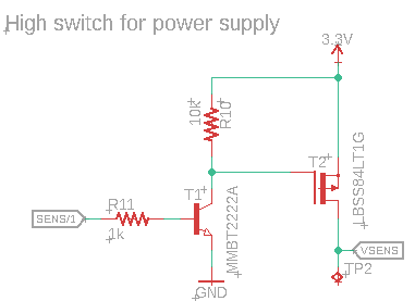
This is done through a high-side switch with a transistor and a mosfet as the schematic shows.
Powered by this VSENS line, the sensors mounted on the Smart Plant are:
- Soil moisture. This sensor is based on the capacitive behavior the soil has at different moisture levels. This is converted through the internal circuit on a voltage level in the range of 0-3.3V that is read by the ESP32 ADC1_1 (GPIO1).
- Ambient light. Through the previous board iterations, I tested different techniques (digital sensors like the MAX44009, photodiodes, and photoresistors). I finally chose the digital sensor VEML7700-TR for simplicity on calibrated data (you still have to define the gain, but it's quite simpler) and the right-angle package compatibility.
- Air temperature & humidity. The chosen sensor is the AHT20, a quite small sensor with a digital output through the I2C bus. Its 2x2mm dimensions had very little impact on the PCB footprint but forced me to outsource the assembly of the boards.
- Battery level. For measuring the battery level, the Smart Plant integrates the MAX17048. This sensor measures the voltage of the LiPo cell and does the math to get an estimative percentage of the battery level.
E-paper display
For low-consumption and aesthetic reasons, the chosen panel where to display the plant's health was an e-ink device. These displays only require power to change the displayed information, and the version I mounted supports partial refresh (meaning even less power consumption), and is connected through a 24-pin FPC clamp connector to the rest of the board.
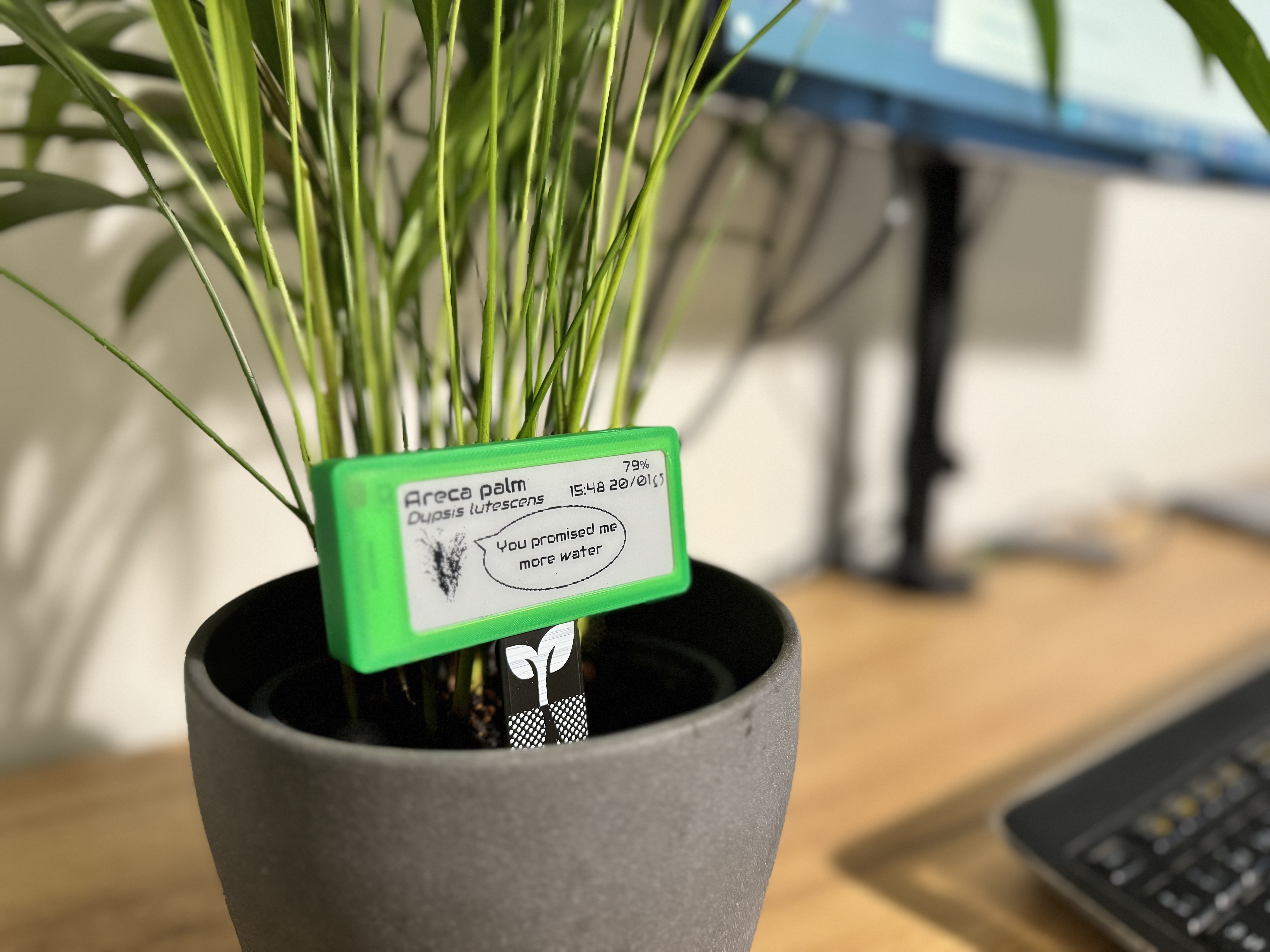
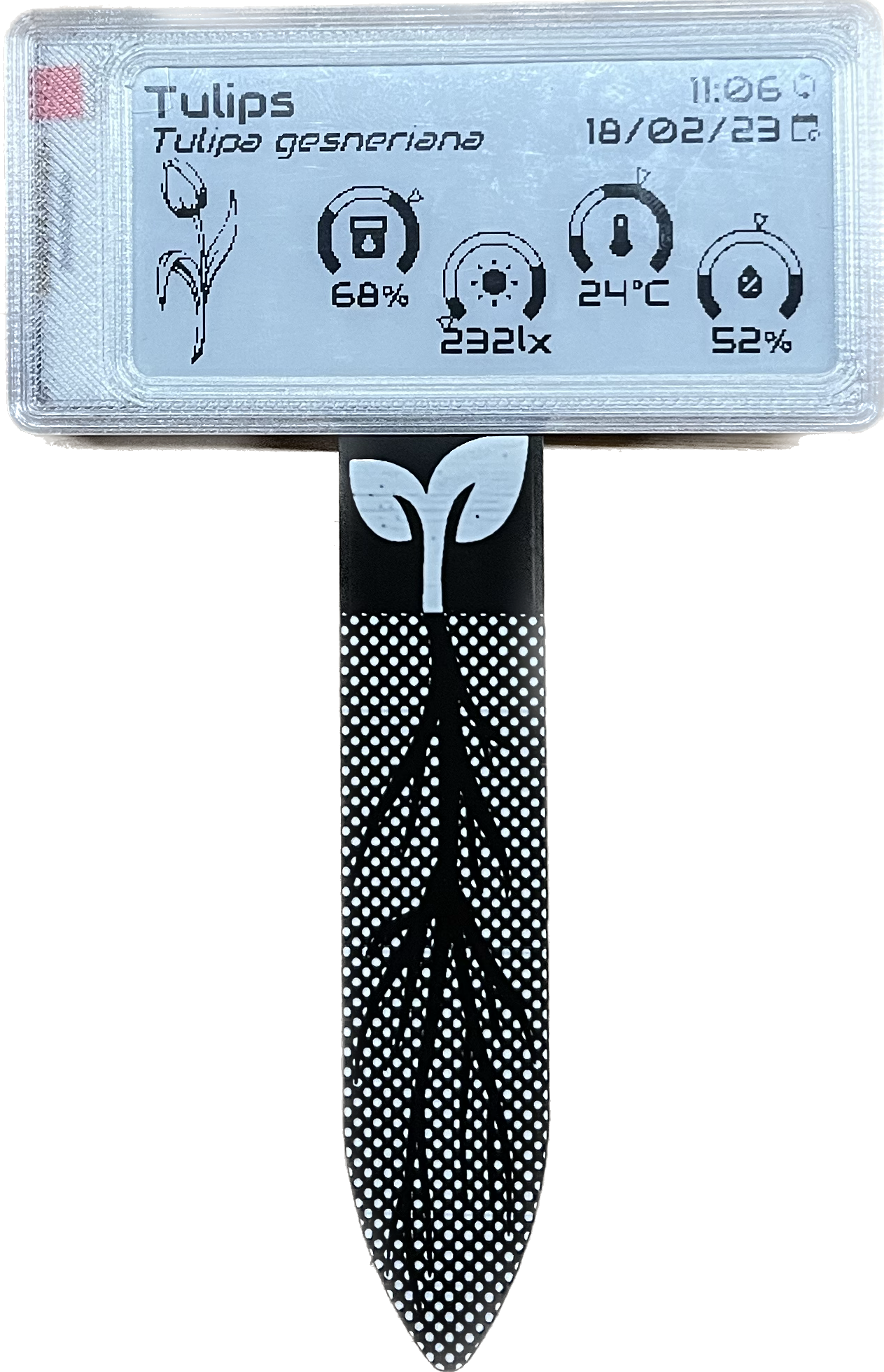
 Now, for the displayed information I created a background titled with the name of the plant, the latin name in subtitled, an image of it, and a series of gauges filled with a recommended range of values where to keep the plant's environmental conditions.
Because I wanted to make fast customized backgrounds for any kind of plant I wanted, I made a Python script that generates a 296x128 pixels image given a configuration YAML file where I state variables of interest (name, latin name, image path, and recommendable ranges for soil moisture, light, temperature and air humidity).
Power management
One of the critical points that I asked for this new design was the low power consumption, achievable only through entering the ESP32 into deep-sleep modes when not reading and powering down all the sensors, as mentioned before. Additionally, the Smart Plant integrates a low power-consuming LDO voltage regulator for bringing the battery voltage into the ESP32's 3.3V needed: the RT9080, capable of delivering up to 600mA and with a low quiescent current as low as 2μA.
As an alternative way to recharge the battery to the USB-C port, a solar panel can be soldered to the exposed pads (so they are in parallel to the USB-C). This way the time in between recharges can be extended depending on the environmental light that can charge the battery.
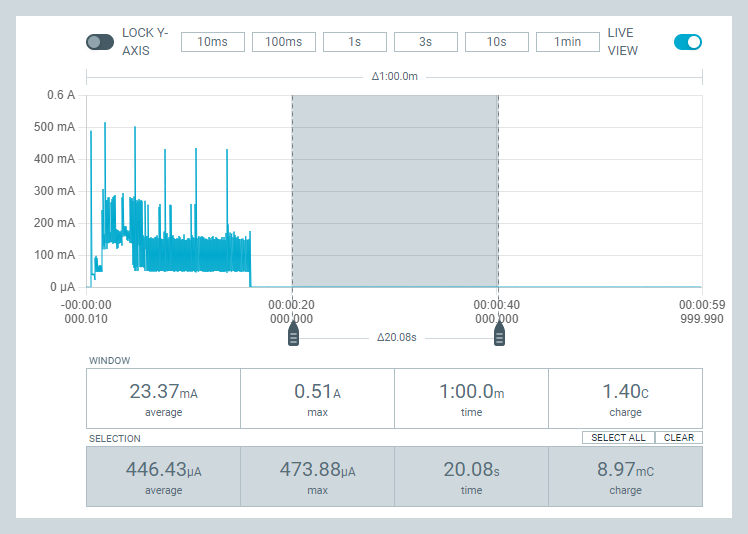
For the bench tests, performed with a Nordic PPK2 board, I configured the board to be awake 10s and into a deep-sleep mode for 1h. The results were pretty good, achieving an average of 450-500μA in deep-sleep mode and a combined consumption of 1mA per hour. This translates into approximately 5-6 weeks of usage for a 1000mAh battery updating the display (and the Home Assistant) each hour.
Extended version log:
V0R1:
I started by making a breadboard behaving as a "shield" for the LILYGO TTGO T5 V2.3.1_2.13 Inch E-Paper where I could plug a capacitive soil moisture sensor and two I2C modules for ambient light (MAX44009) and temperature & humidity (BMP280) measurement.
 |
 |
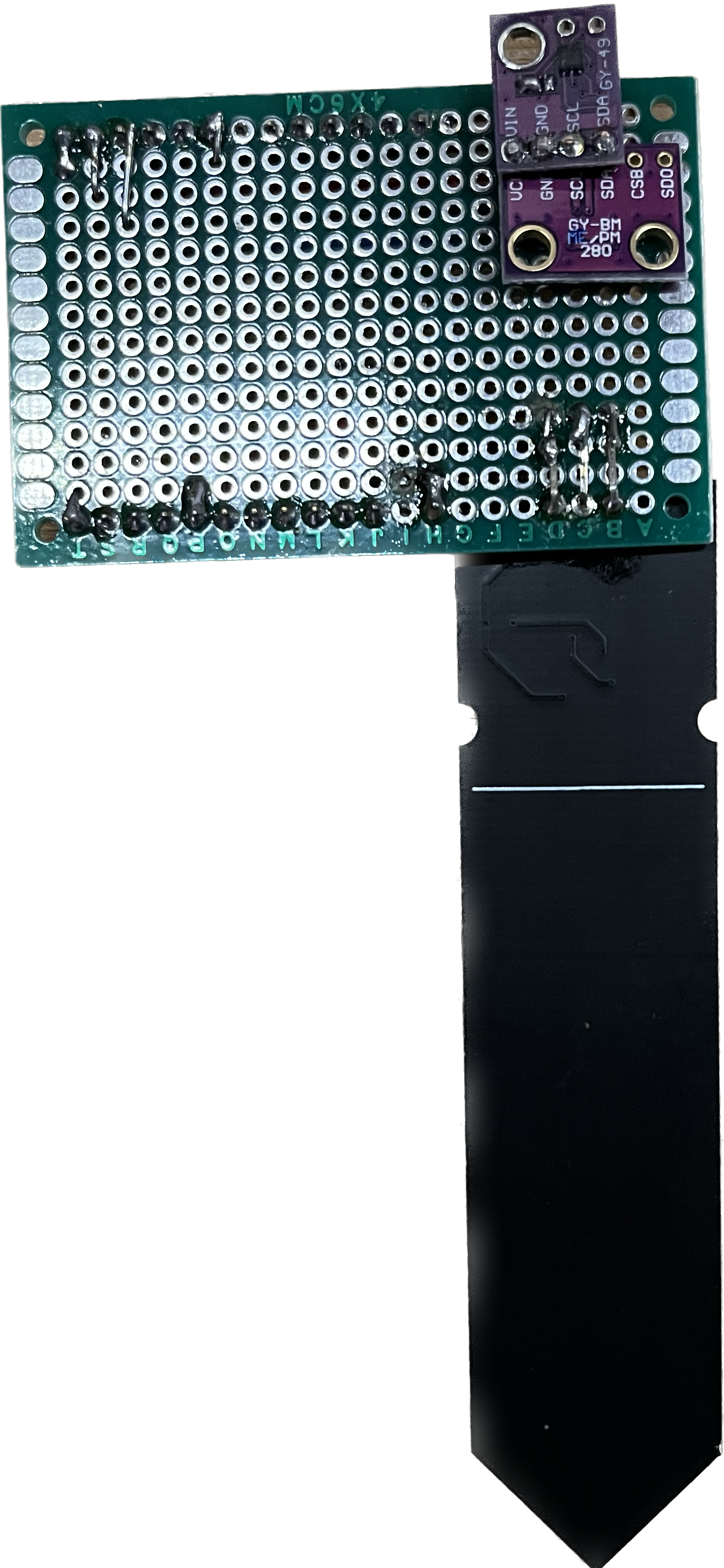 |
| Smart Plant V0R1 assembled | Smart Plant V0R1 front | Smart Plant V0R1 back |
V0R2:
The breadboard worked so I moved to a customized PCB, this time embedding a 555-based circuit for the capacitive soil moisture sensor and the ambient sensors (light and temperature). On this prototype, I also added a circuit to allow the selective powering of the sensors, with the aim of bringing down the total power consumption after entering the microcontroller into a deep-sleep mode.
 |  |  |
| Smart Plant V0R2 assembled | Smart Plant V0R2 front | Smart Plant V0R2 back |
I also added a circuit for directly reading the soil conductivity through two electrodes (similar to what the Mi Flora does), but after testing it I ended up discarding it, for not finding a good solution to the electrolysis on the terminals that happened after some months of usage. I even added stainless steel rivets to cover the exposure of areas that could get affected, but with enough time it also got affected.
Since it wasn't a measurement parameter that I would miss that much, I moved with the rest of the board functionalities working (or rewiring and fixing the errors in order to get them working).
V1R1:
After the trial and error path followed on Version 0 boards, I moved into a more custom PCB, aiming for more aesthetics-driven board
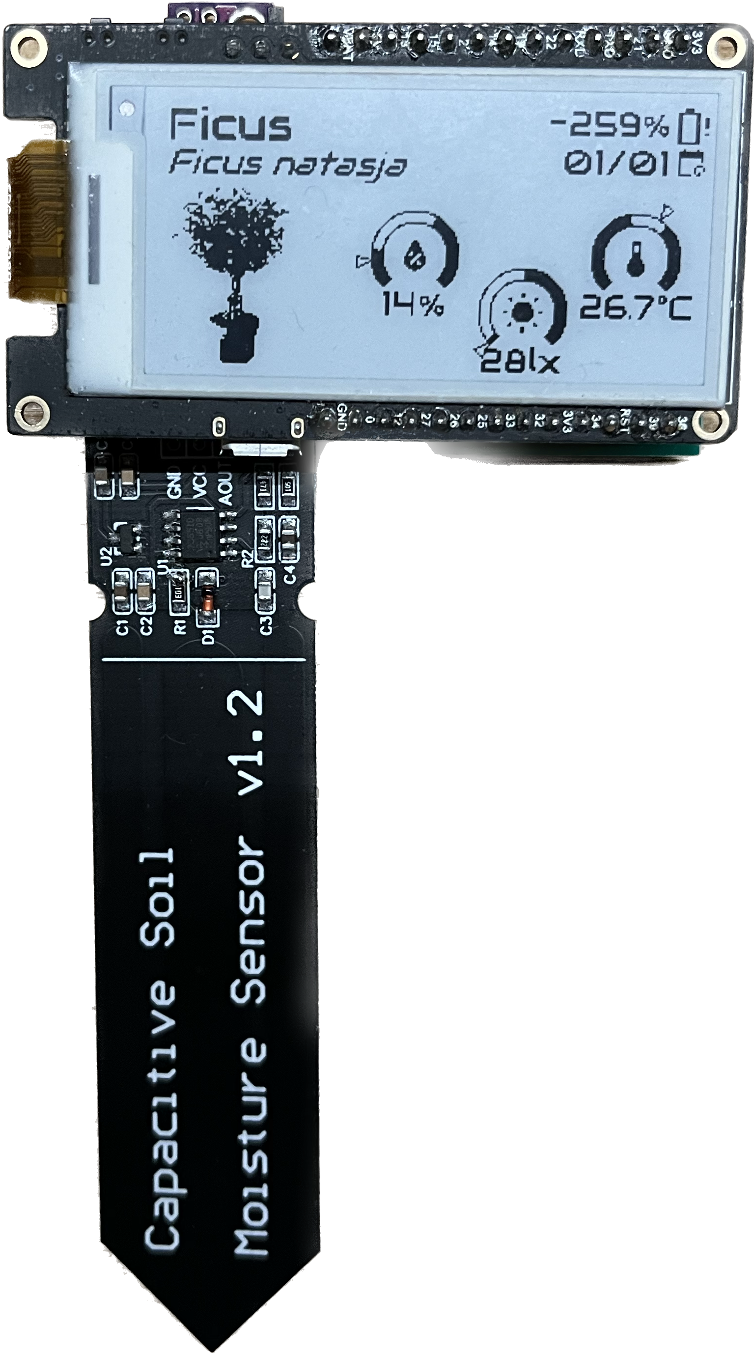
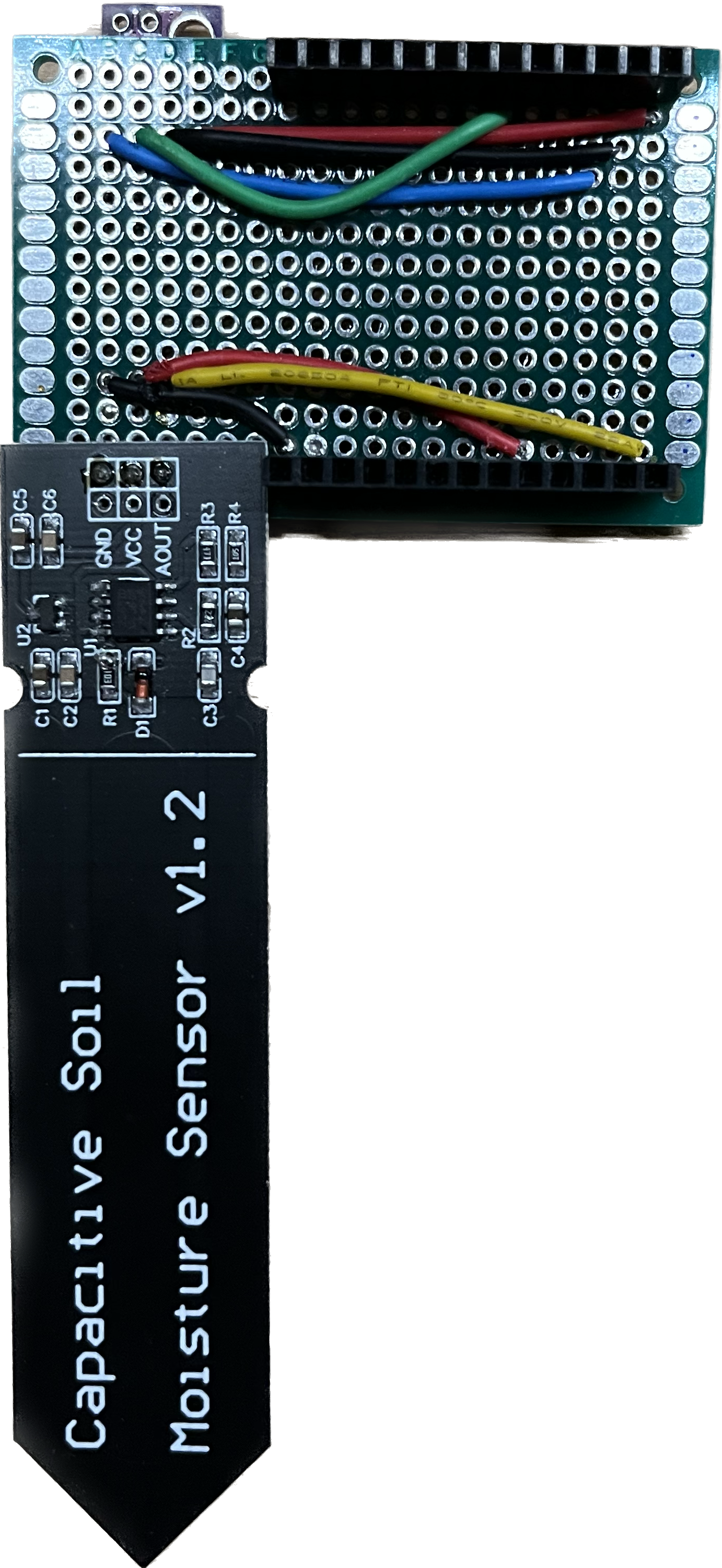
 |  |  |
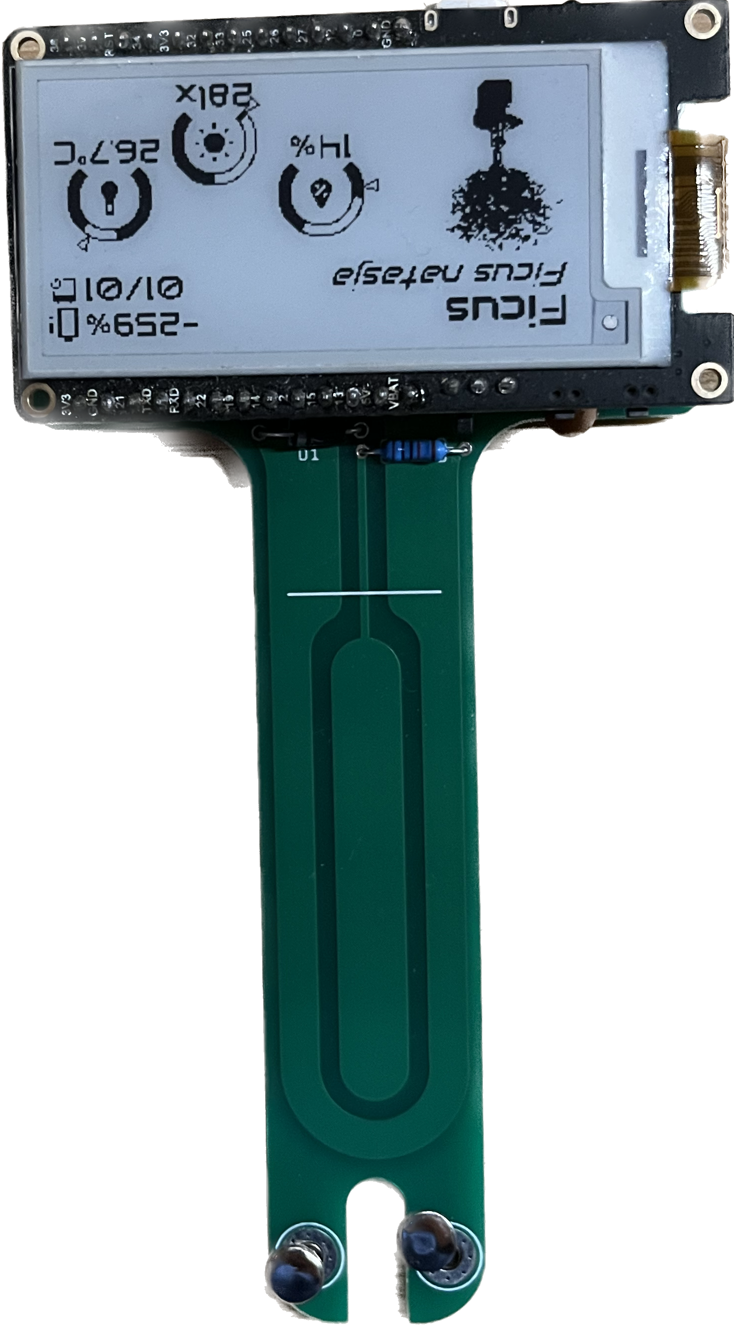
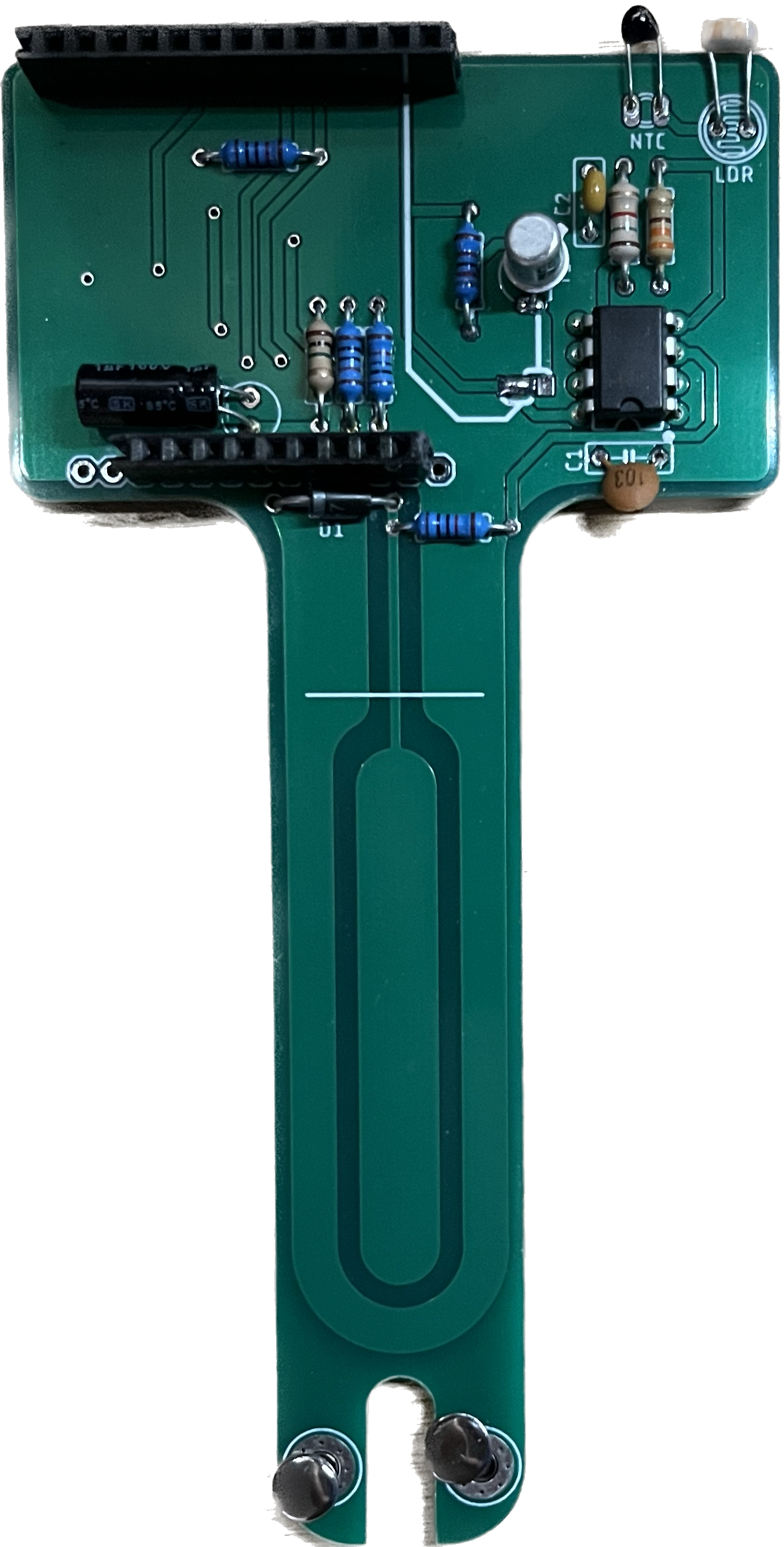
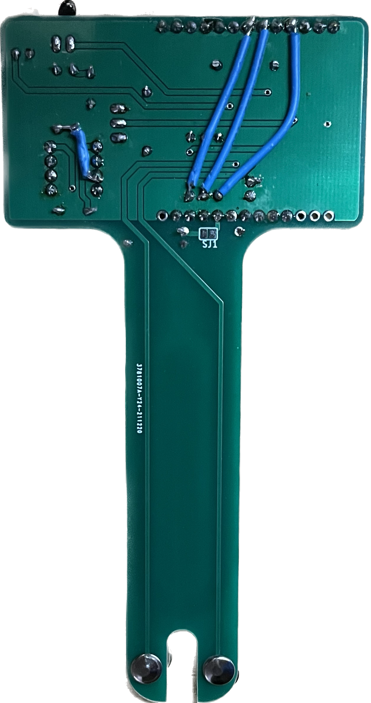
| Smart Plant V1R1 assembled | Smart Plant V1R1 front | Smart Plant V1R1 back |
On this board, I integrated an ESP32-S module and I upscaled the e-paper from the 2.13" on the TTGO to a more easy-to-read 2.9" display, together with a LiPo charging circuit and some integrated sensors: a built-in capacitive soil moisture probe, a photodiode, the AHT20 for air temperature & humidity measurement, and a voltage divider for monitoring the battery voltage level.
However, there was an initial small error on the PCB routing that affected the LiPo charging circuit. Since the error was very located, and in order to not throw away 5 prototypes working fine (except for the LiPo charging circuit) I designed a "patch" board that could be soldered over and that would fix the problem.
V1R2:
On this new revision, the main change was the power module bug fixing together with the replacement of the light sensor: from a photodiode to a photoresistor.
 | | 
|
| Smart Plant V1R2 assembled | Smart Plant V1R2 front | Smart Plant V1R2 back |
This was also the first batch of boards that I started selling through Tindie, with a total of 20 boards sold to my very first early-adopter customers :)
V2R1:
Since I felt that the Smart Plant still had some room for improvement, I kept pushing the design to the next stage.
 | |  |
| Smart Plant V1R2 assembled | Smart Plant V1R2 front | Smart Plant V1R2 back |
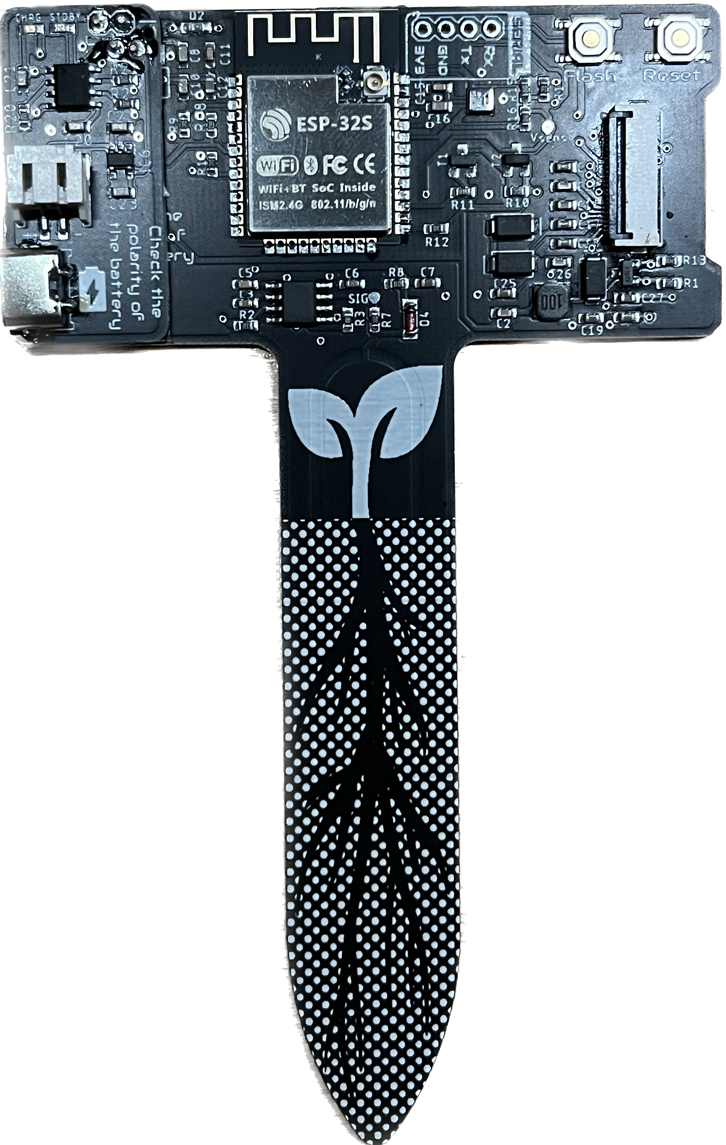
In this new version, I replaced the previous ESP32-S module with an ESP32-S2-MINI-1-N4R2 module, more compact and with an integrated USB driver, removing the need to upload the first code through the UART port.
As I was not 100% happy with the light sensor, I tested the VEML7700-TR digital sensor, capable of providing measurements already in lux, with previous gain adjustment.
In previous versions, I was also monitoring the battery voltage level directly through an analog input to the ESP32, but again, the non-linearity between the voltage level and the battery "percentage" made it complicated to display an accurate value. Therefore I decided to try with the MAX17048, an IC specifically designed to monitor LiPo's levels and deliver the value in percentage.