This project is modified from the reference circuit of FP5139 switching regulator control IC. Its original design is a asynchronous buck-boost converter. To improve overall working efficiency, a gate-driver is added and use two N-Channel MOSFETs to form a synchronous buck converter for high current battery-powered application.
FP5139 switching regulator :
The switching frequency is about 50kHz, selected by the components C10 and R12. The output voltage is defined by (1 + R14/R15) x Vref, where Vref = 0.5V. The desired output voltage is slightly higher the COB LED's maximum voltage. When this high-power COB LED is turn-on, the forward-voltage will increase with its temperature. The additional OpAmp U2 provides constant current function in which ensure the LED will not over drive. Please be noted that the brightness of LED is proportional to the current supplied.
Gate Driver :
U1 is a gate-driver in which provides both invert and non-invert outputs to drive N-Channel MOSFETs, with typical dead-time 400ns to prevent two MOSFETs turn on at the same time. There is one input for PWM signal, in which connects to FP5139's PWM output. During ON-cycle, MOSFET Q1 conducts and current flow through inductor L1 and the load. The energy stored in inductor L1 is discharge to the load via MOSFET Q2 when PWM is at OFF-cycle. This improves the efficiency when only use a diode for discharge the process, due to voltage drop across the diode.
Constant Current Control :
There is a shunt-resistor R18 connected in series with load. So it can measure the amount of current used by the COB LED. The voltage across this shunt-resistor is amplified by OpAmp U2-A. It is about 10.1 times amplification in voltage. The desired constant current is at 6.5A. For the 10mOhm shunt-resistor, the voltage drop will be 65mV and the output for the OpAmp is about 0.65V.
The OpAmp U2-B is configured as a sawtooth waveform generator. The OpAmp's negative input connects to a variable resistor R21, in which provides reference voltage from 0 to 2V. When the voltage at its positive input is high than negative input, the OpAmp's output will ramp up, otherwise it will decrease to zero. If the ramp up voltage is high enough to turn on LED D6, the voltage at FB pin of FP5139 will also increase, thus FP5139 will decrease its PWM duty-cycle, and the output current will decrease at the same time. FP5139 will always keep its FB pin at 0.5V by adjusting the duty-cycle of output PWM signal.
The variable resistor R21 can be used to adjust the desired constant current, while turning in clockwise direction to decrease current value and the anti-clockwise direction to increase the desired current value.
Under Voltage Protection :
Zener diodes D5 and D7 are used to protect the input battery from under voltage condition. The total zener voltage is 22V. Therefore the battery's voltage must higher than 22V+0.6V(Q4 base forward voltage), before the switching regulator starts operation.
On board voltage regulation :
The ICs on board is using a simple zener diode (D4) and NPN transistor Q3 for the 12Vdc power regulation. The actual voltage should be 11.4V.
Component Selection :
- All electrolytic capacitors must use LowESR type. This minimize the energy lost inside these capacitor due to internal resistance
- N-Channel MOSFETs need to have very very small turn-on resistance and low gate capacitance. This helps to enhance fast turn on and off switching speed and low lost on the turn-on resistance
- The Inductor L1, a recommended part is Bourns Inc. 2200LL-470-V-RC. Core material : Sendust. A good inductor improves the efficiency of switching circuits
- PCB layout is another factor can improve efficiency. Always use thick trace and ground copper pour for both input paths and output paths. Place all key components such as MOSFETs, Inductor, Electrolytic Capacitors as close as possible. These helps to minimize the current loop paths.
- System Wiring is also important. Use correct number of wire gauge for both the battery and COB LED connection. Try to miminize the length of cables. Those wires carries below 10 Amps. of current flow.
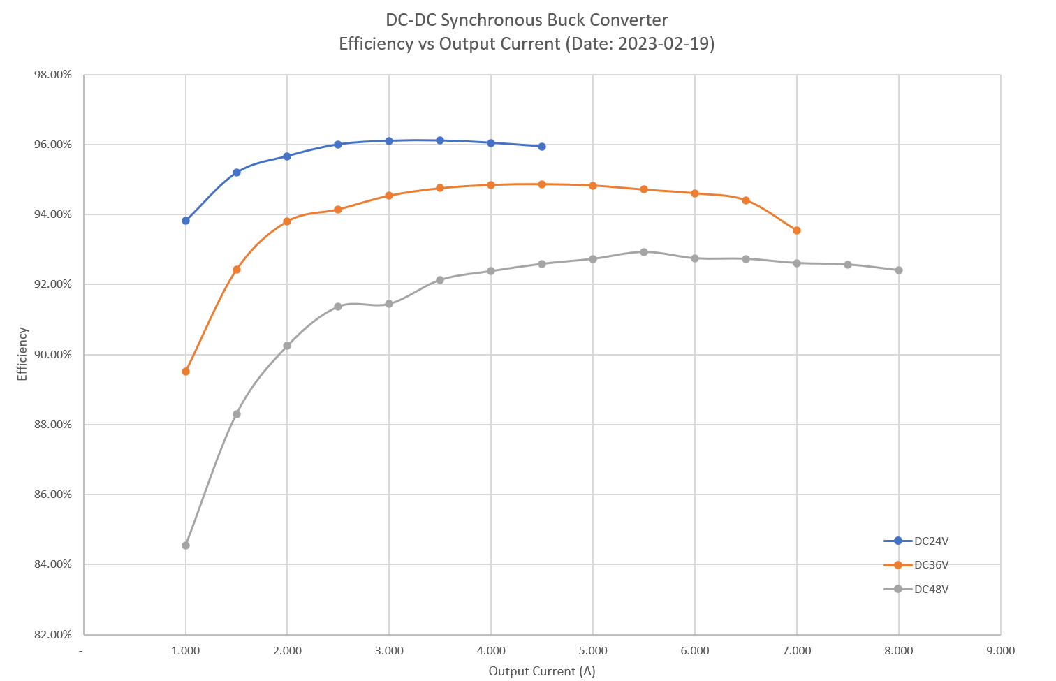
Efficiency Chart :

 Kevin LO