I had written in a previous log that the navigation switch had quite heavy chatter. What's weird is that it only happened for 3 of its 5 positions. I first thought it was mechanical, but ruled it out after measuring with an oscilloscope on a standalone navigation switch.
The second possible cause was crosstalk between the lines. This was quite unlikely as the affected lines weren't that close to each other.
The third cause could be bad contacts in either the 6PDT switch or the JST connector. I first thought it was the switch because bypassing it and connecting the navigation switch directly to the switch matrix eliminated chatter. The issue with this "solution" is that it was impossible to switch out to the horizontal encoder without desoldering.
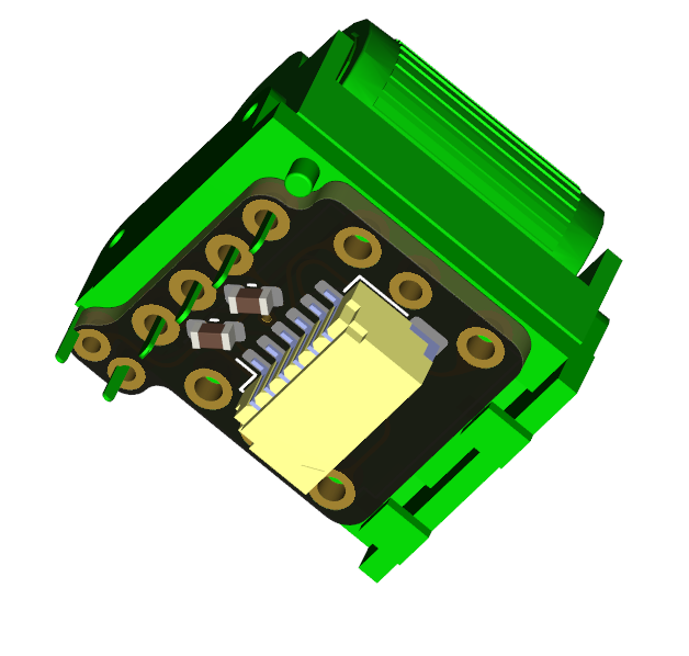
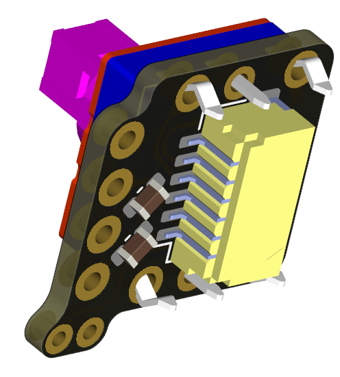
Wait a second... The horizontal encoder... Well, that was the cause of everything: both the navigation switch and the horizontal encoder were using the same interface board (presented in the first log). This interface board has capacitors between the A/C and B/C lines of the rotary encoder for very crude hardware debouncing. The thing is, when the navigation switch was selected, the capacitors were then between the UP, DOWN and CENTER lines, which meant that activating one charged the capacitor, inducing a voltage spike in the other lines.
The solution is then very simple, which is to not populate the capacitors when soldering the navigation switch on the interface board.
You can see below the 2 capacitors that are used when the horizontal encoder is soldered.

They should be removed when soldering the navigation switch

 Nguyen Vincent
Discussions
Become a Hackaday.io Member
Create an account to leave a comment. Already have an account? Log In.