 Peter
PeterSo, now the components of the control unit are mounted together. The next step is to implement the NOP command (page 39 of the circuit diagram) and the uCommand board (page 20 of the circuit diagram). The two boards will be placed on two of the bus connectors of the bus-module on top of the control unit:

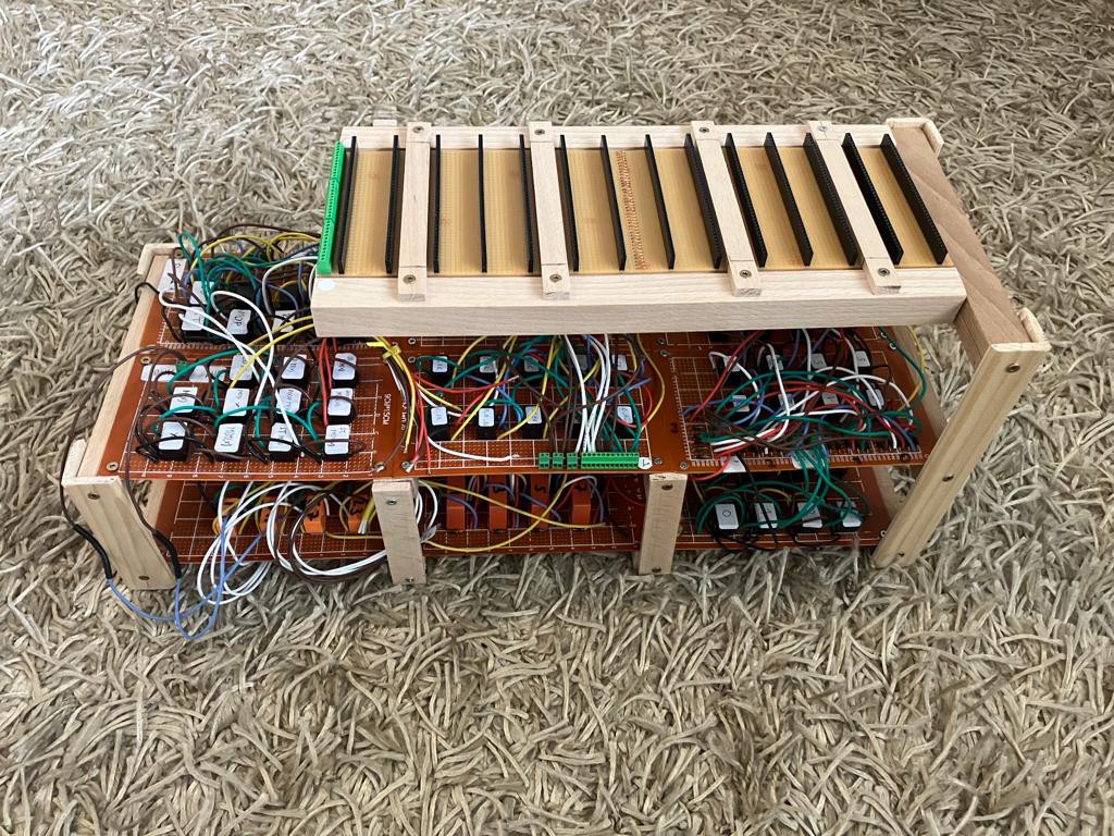
And then the tests of the control unit will start. A new logic analyzer is avaliable (16 channels, a cheap variant is enough for this very slow system) and an Arduino will be used as a clock for the system.
Discussions
Become a Hackaday.io Member
Create an account to leave a comment. Already have an account? Log In.