 Peter
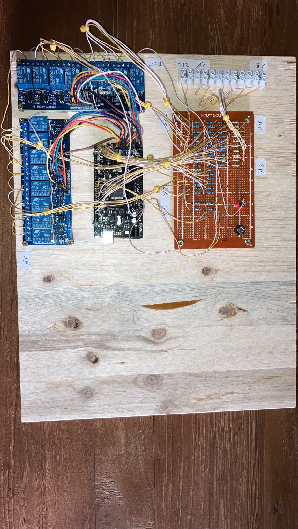
PeterSo, here you see the complete system memory of the relay computer...or, a relay CPU with an arduino memory. The software ist tested, the block terminals are the connections to the relay CPU data bus, the adress bus, the read line and the write line. If the read line is active the memory will write out the stored word defined by the adress input, if the write line is active the memory stores the data defined by the data bus. The board with the resistors is necessary because the relay CPU is working with 24V, the arduino uses only 5V.
Discussions
Become a Hackaday.io Member
Create an account to leave a comment. Already have an account? Log In.