 Peter
PeterSo, the instruction register is now connected to the instruction decoder. I had to buy a new soldering station, my very cheap, old one was a little bit overwhelmed.
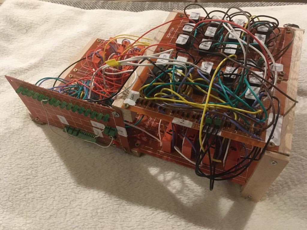
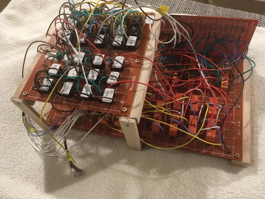
Here you see the pictures of the new modul. The next week I will test it, write the opcode and adressmode of all commands into the data input of the instruction register and I will see if everything works well.
The next module will be the register of the control unit state machine...you find it on page 21 of the circuit diagram.
Discussions
Become a Hackaday.io Member
Create an account to leave a comment. Already have an account? Log In.