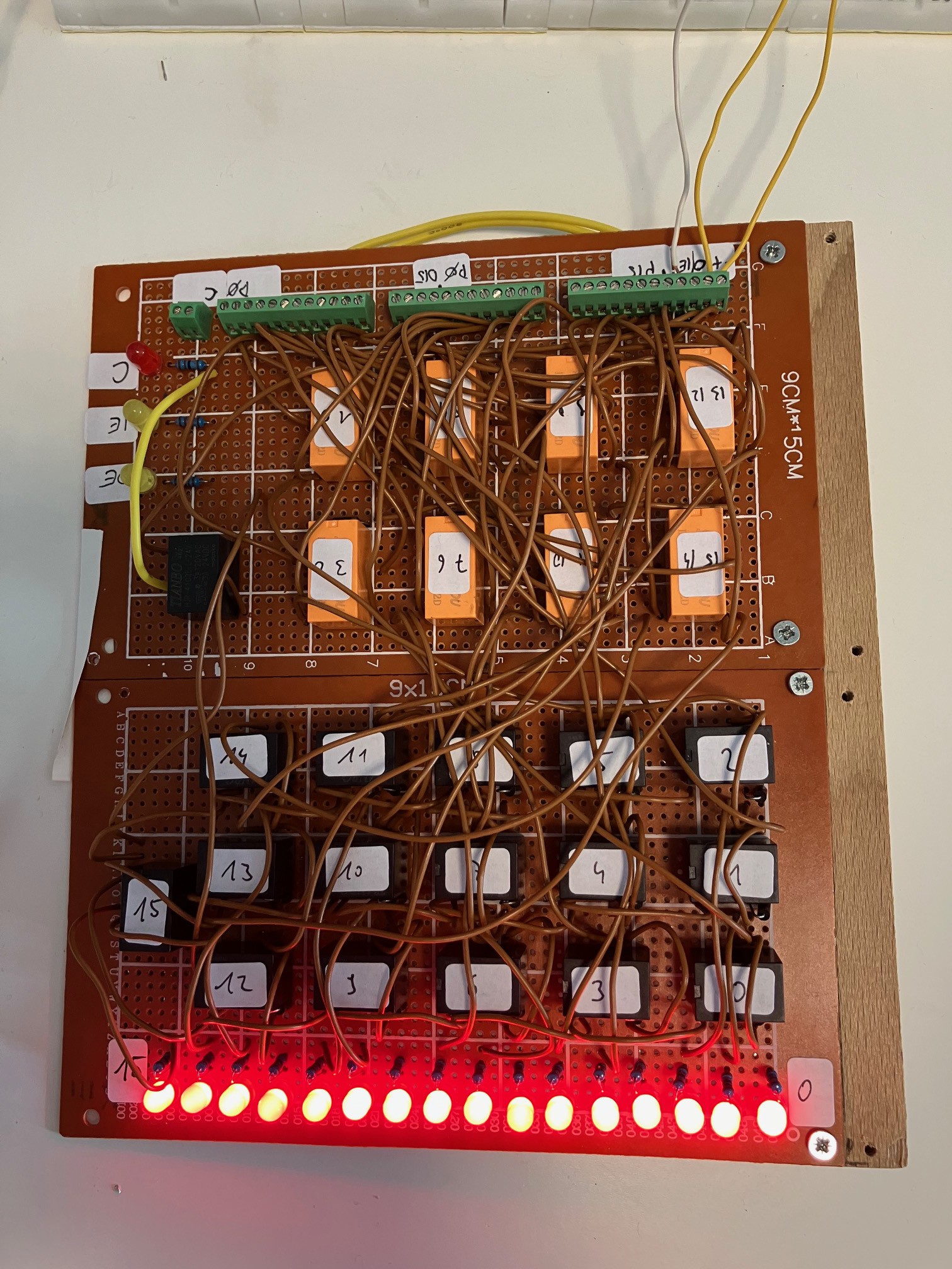
So, the 16 bit accumulator register, which the register for all mathematical, all store and all load operations, is finished and tested. The next step is to connect the register to the system...

The 16 black relays with numbers are responsible for storing the bit values (by holding themself in an active state), the black relay without a number releases the VCC (for clearing the stored value) and the orange relays are responsible for Input and Output to/from the databus.
 Peter
Peter
Discussions
Become a Hackaday.io Member
Create an account to leave a comment. Already have an account? Log In.