 Peter
PeterNo the relay system has an 16 bit output register...
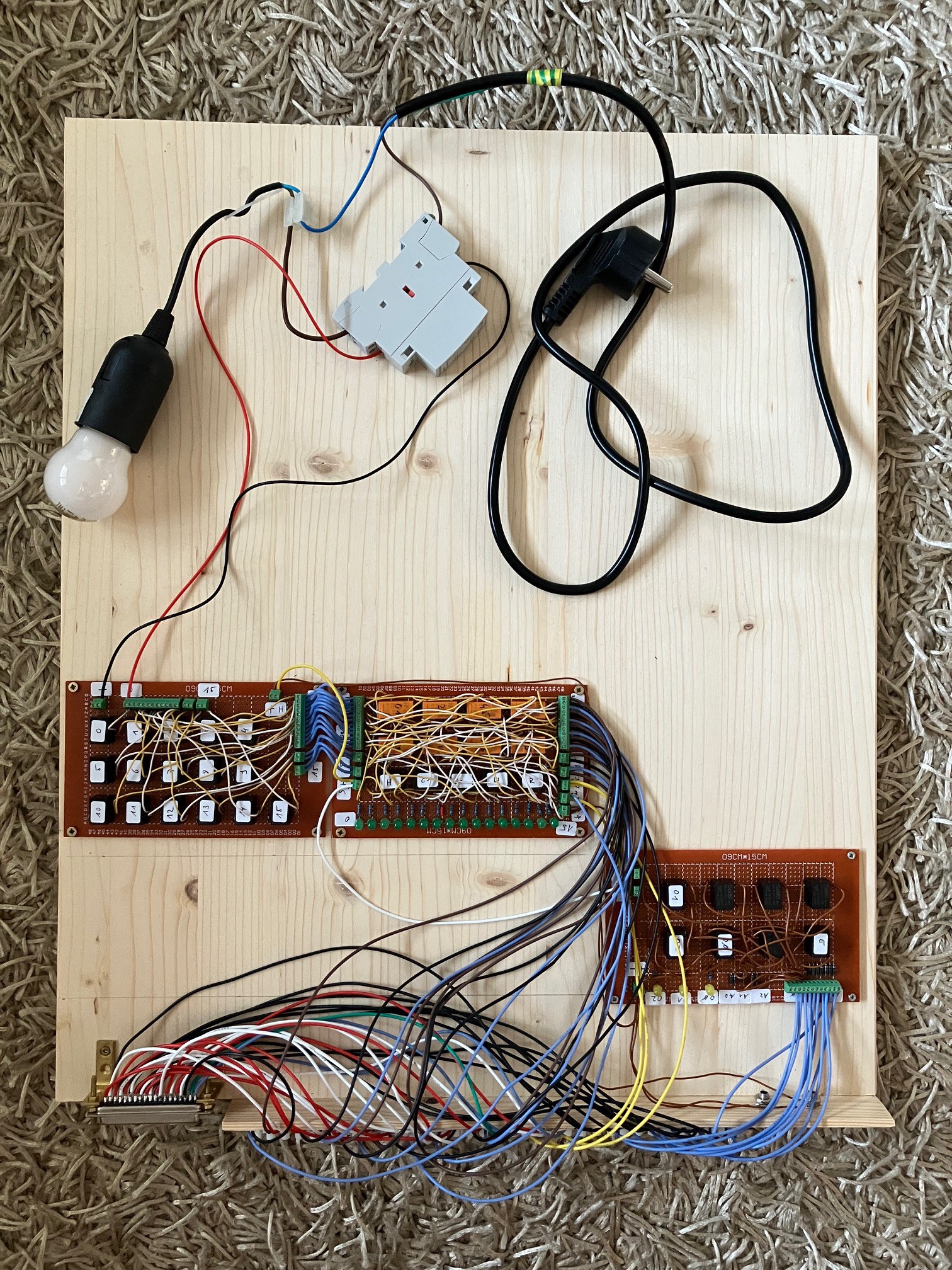
The board on the right side is the decoder for three registers...
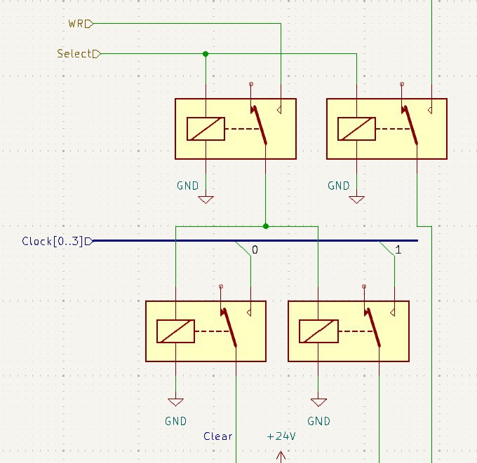
I had to connect a signal directly to the I/O-board connector, bypassing the control-line timing module. The Output register has to be deleted during Clock 0 if WE and the Select of the register is active, but the WE connected to the memory is only valid during Clock 1.
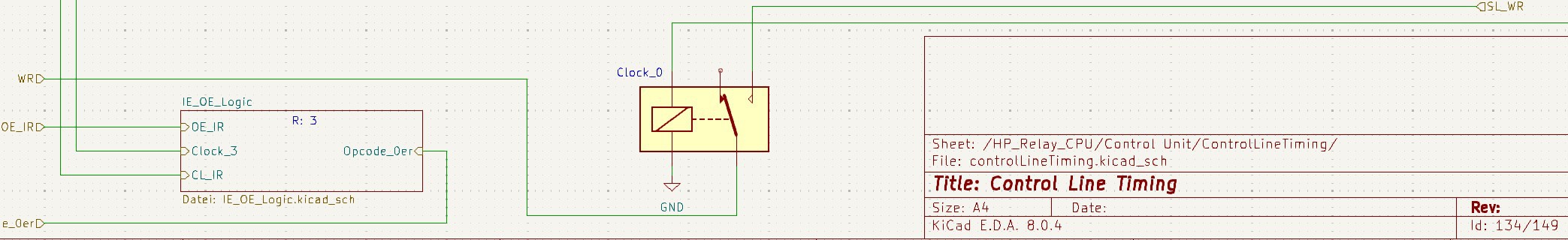
But the output register needs WE during Clock 0:
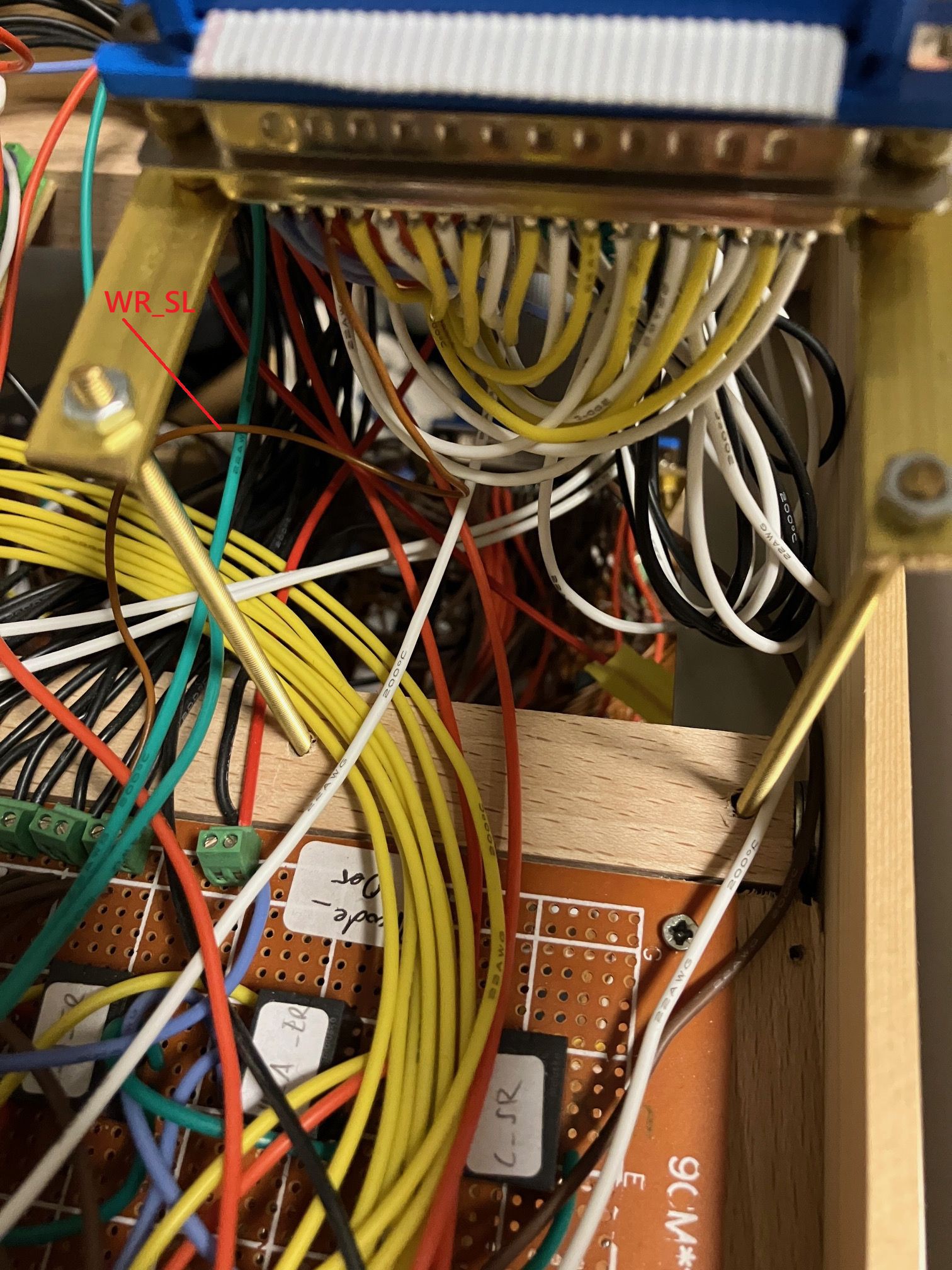
So, I had to connect the original WE_SL to the connector:
And I had to work on the timing of the relay system...
Standard:
int takt1 = 10;
int takt2 = 20;
int takt3 = 10;
int takt4 = 10;
int delayTime = 5;
And now for the output register:
int takt1 = 15;
int takt2 = 15;
int takt3 = 10;
int takt4 = 10;
int delayTime = 5;
Discussions
Become a Hackaday.io Member
Create an account to leave a comment. Already have an account? Log In.