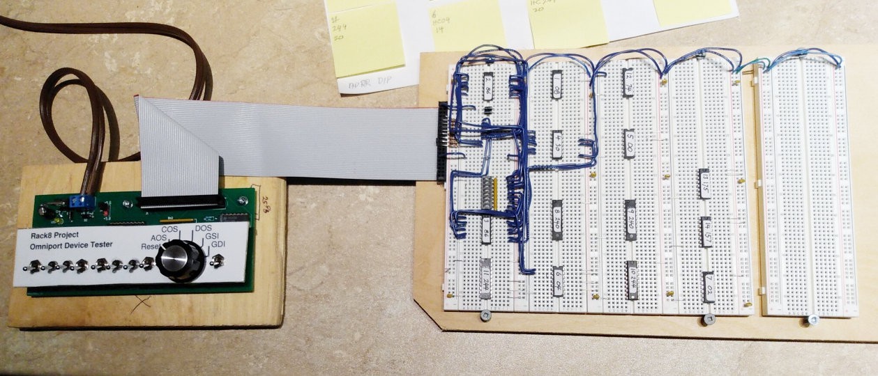
With the schematic for the GPI board in hand, the next order of business was breadboarding it to make sure it worked. The photo below shows GPI breadboard near the start of testing. At that point the goal was to get the device selection logic working. To the left of the breadboard is the OmniTester, from the previous log.

It wasn't all that difficult to get the GPI working - It was pretty much just replicating the ideas behind the MCM schematic - and so in short order it was looking good.
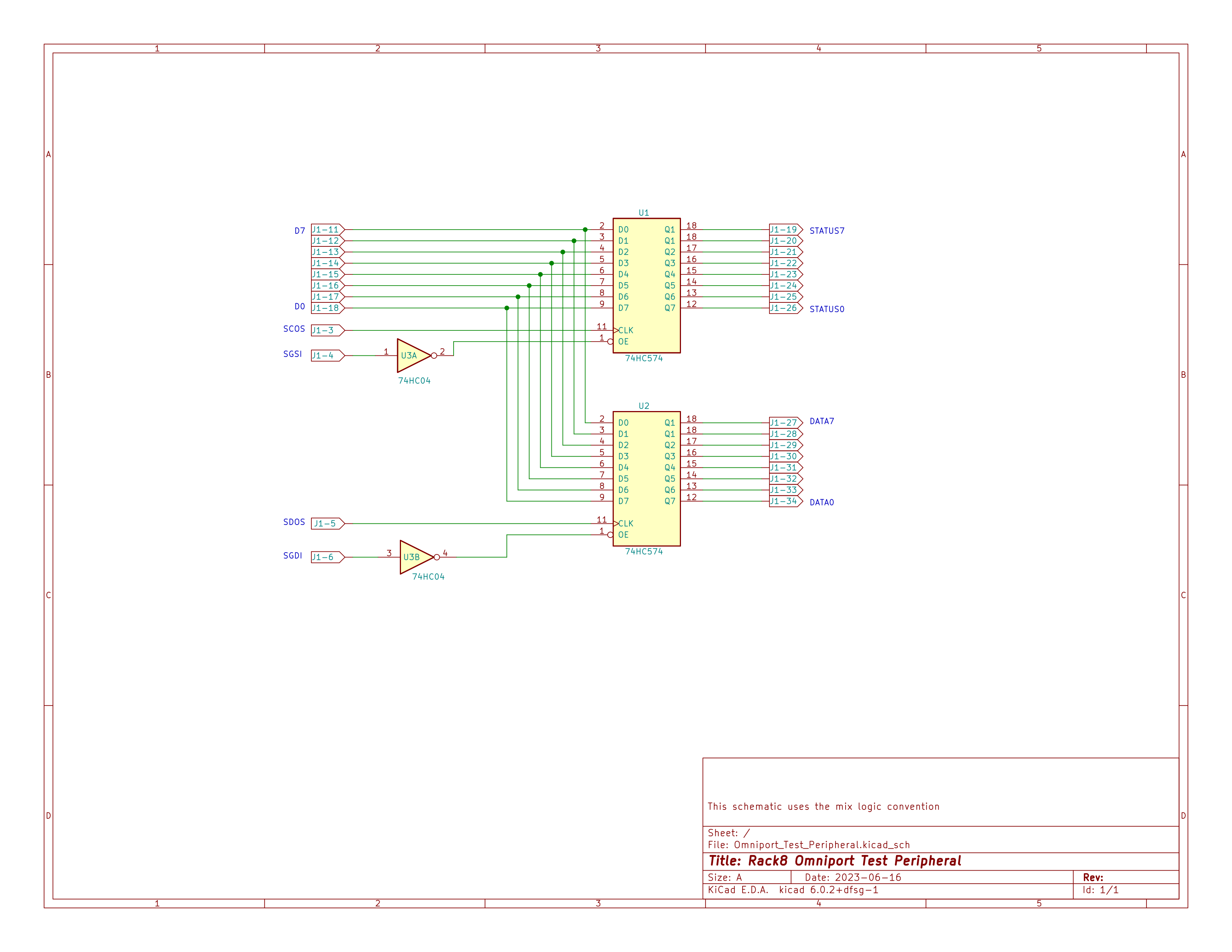
But then an actual peripheral was required to make sure it worked as intended, which resulted in the following schematic, which is pretty much "Hello World" as an Omniport Peripheral:

consisting of two 8-bit latches and a couple of inverters. When the MCM computer sends a command to the peripheral it is stored in latch U1. When the computer ask for the device status, the value in U1 is returned. When the MCM computer sends a data byte to the peripheral it is stored in latch U2. And when the computer asks for data from the peripheral the value in U2 is returned. Useless in practical terms, but just fine for verifying operation of the GPI card and the Omniport interface on the Rack8 machine.
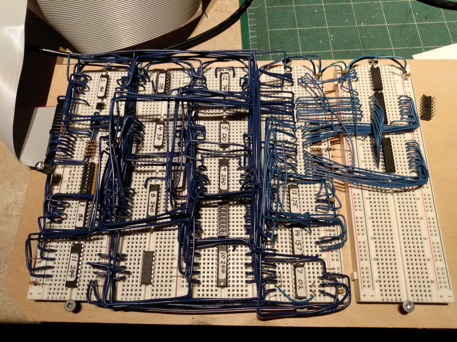
The photo below shows the prototype GPI (the four breadboards on the left) and the test peripheral (the single breadboard on the right). The GPI is connected to the main Rack8 breadboard by the 40 conductor ribbon cable on the left.

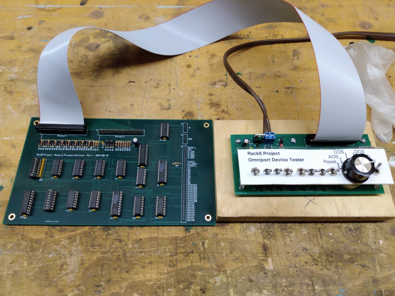
The test peripheral helped establish that the Omniport interface and the GPI were working just fine. With that done, it was time to turn the GPI into a printed circuit board. The photo below shows the printed circuit version of the Rack8 GPI board, connected to the OmniTester. The row of Berg strips on the far right of the PCB are for connection to the eventual peripheral.

Discussions
Become a Hackaday.io Member
Create an account to leave a comment. Already have an account? Log In.