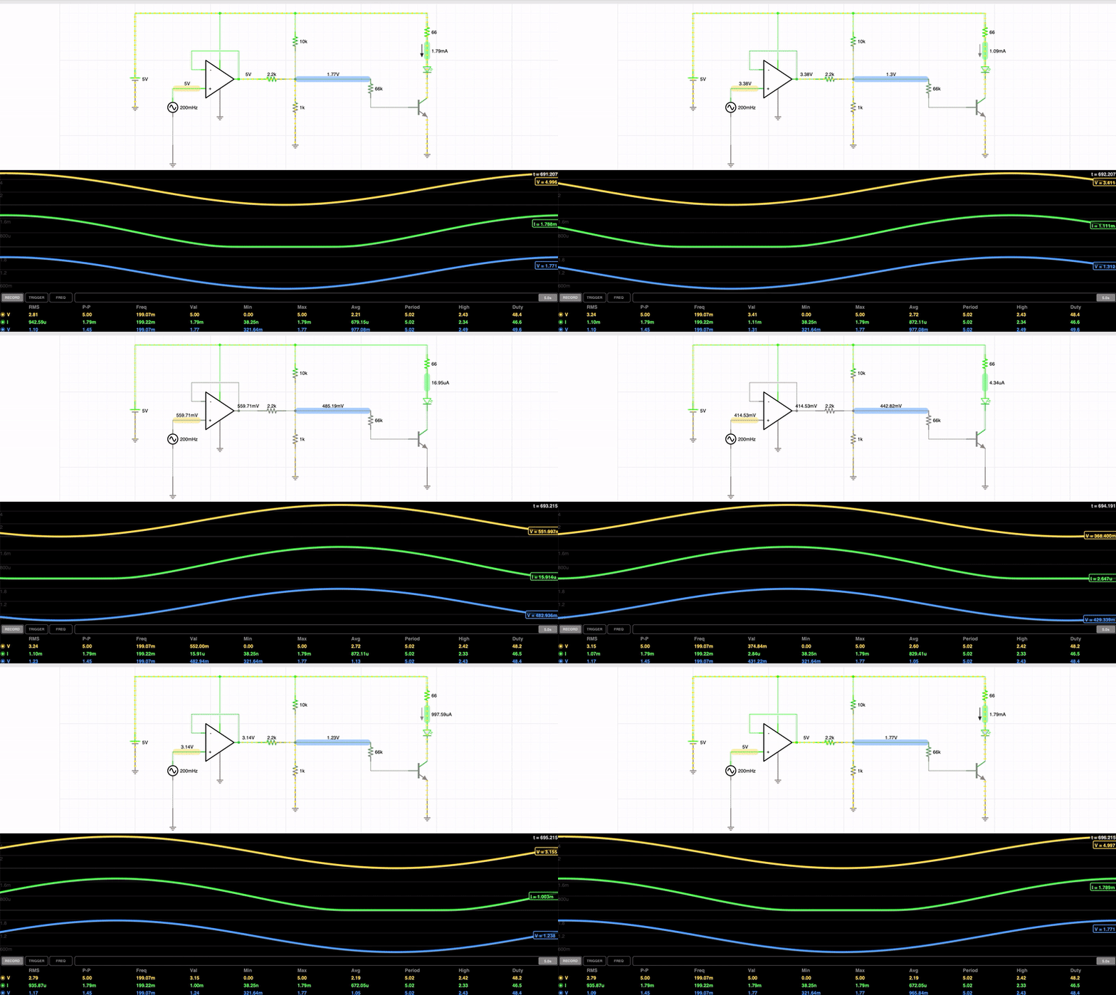
Unlike the Digital IO pins the analog pins have an led driven by an Opamp and Summation circuit that will map the LED to the Voltage. So the LED will glow with the intensity proportional to the Voltage 0-5V
The Analog LED Circuit is as Follows

The Opamp Acts as a high impotence buffer So it does not influence any analog input to the pin. A Summation Network is crated to lower the voltage before it gets fed through a 66k Resistor then into a NPN Transistor to drive the Current to the LED
---------------------------------------------------------------------------------------------------------------------------------------------
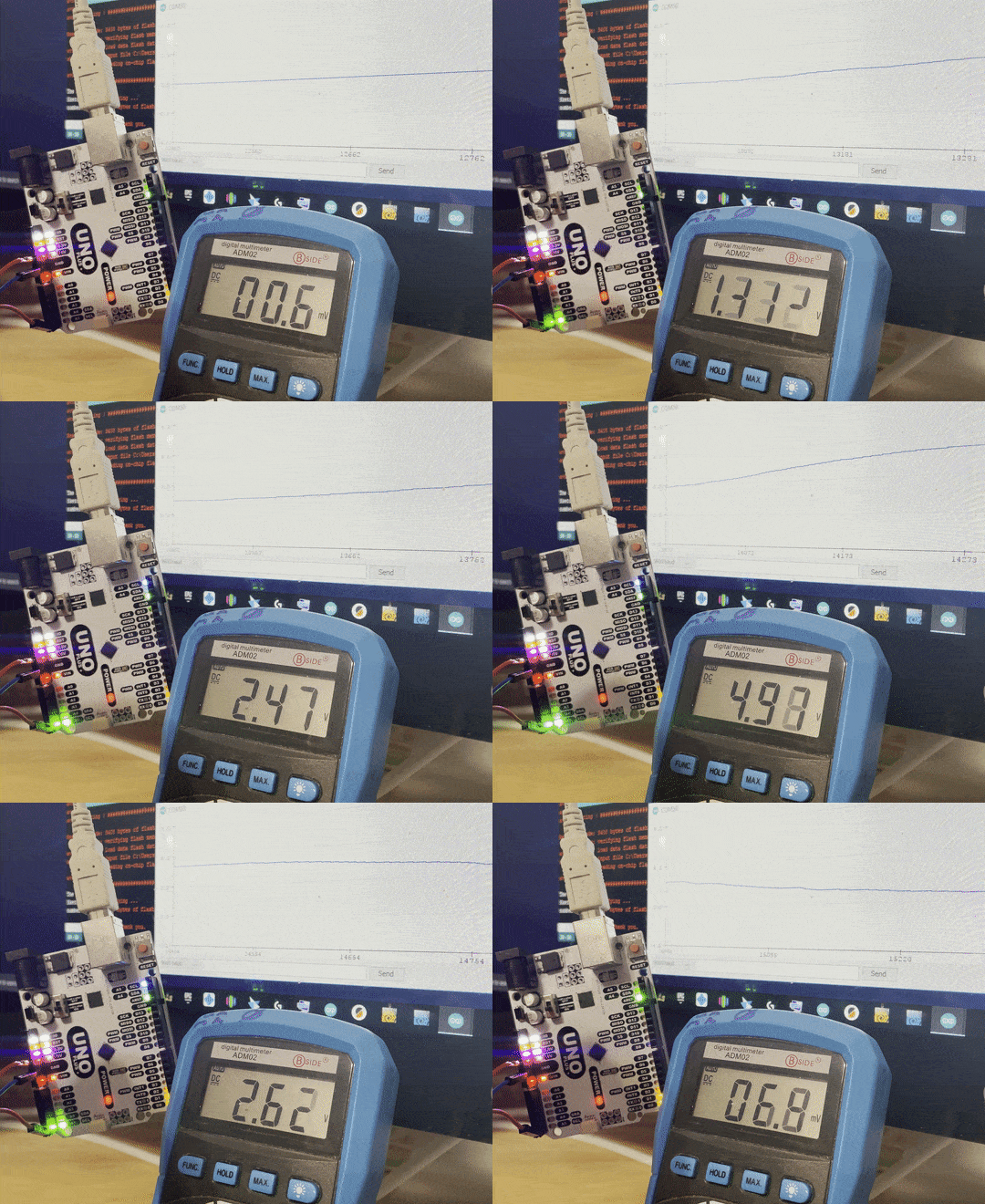
The Real World Test of this circuit show that the current configuration does a decent job of making the pins Voltage to the Intensity of the LED.

 John Loeffler
Discussions
Become a Hackaday.io Member
Create an account to leave a comment. Already have an account? Log In.