Jerry Biehler
-
More Turbos
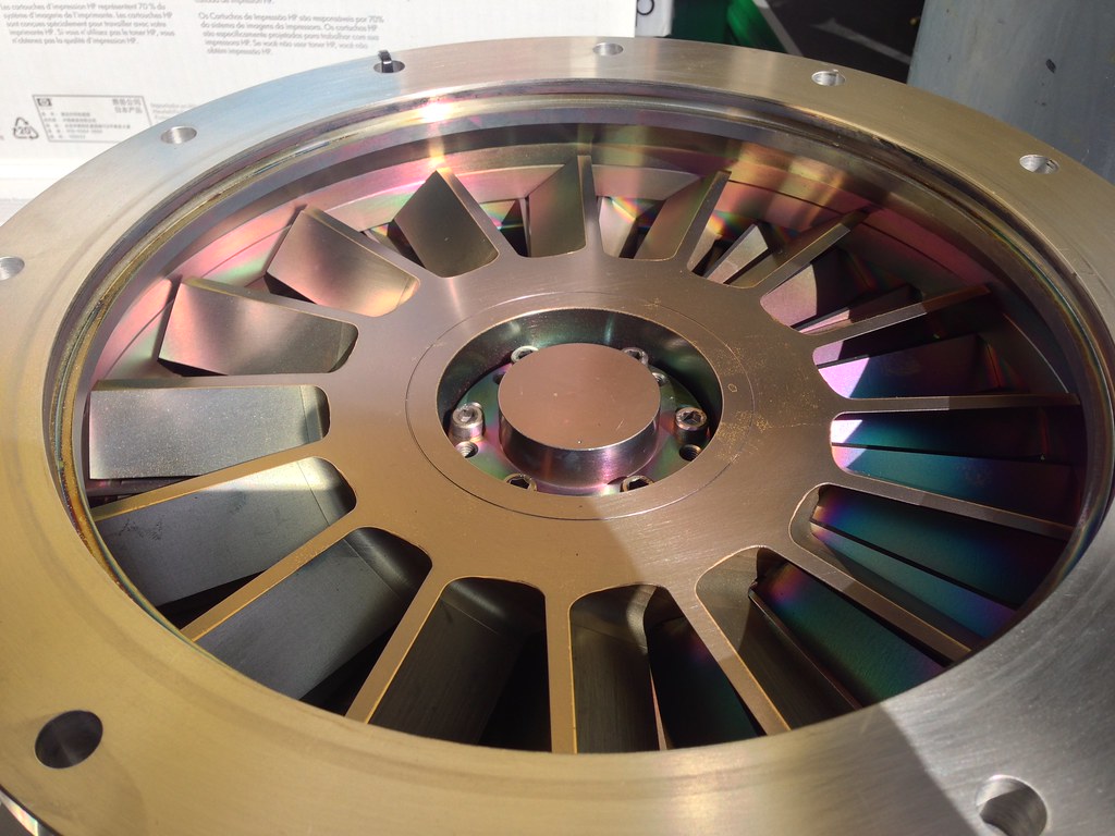
05/19/2014 at 06:38 • 0 commentsI got another turbo pumps, this time a complete set, pump and controller. It is an Osaka Vacuum TG2003 rated for 2000l/s at 24,000 rpm. It is mag lev like the other pumps I had been trying to get going but a little more friendly. I plan on keeping an eye out for another controller for the other 2000l/s pump I have.
![Untitled]()
So, to get this thing on the system is going to take quite a bit of modification. The rotary pump/blower package is going to come off the frame to get the vibration isolated from the turbo. I am also installing a stepper driven gate valve from VAT with a adaptive pressure controller. The gate valve mounts directly to the ISO250K flange on the turbo and receives feedback from a capacitance manometer on the vacuum chamber. The controller can be set for a pressure and the controller with open or close the gate valve to maintain the set pressure in the chamber. Pretty handy for sputtering and plasma processes that work above the high vacuum range.
All of this needs to mount where the diffusion pump was. That was mounted to the system through a 6" port with a ASA flange and a 6" pneumatic gate valve in between. I am leaving the gate valve in place, it closes very quickly and will be useful to cut off the turbo in case of a high pressure event. The stepper driven valve won't be of much use for this, it takes up to 10 seconds to close.
To mount the pump/valve to the existing valve I need an adapter that will go from the ISO250K on the stepper valve to the ASA 6" on the pneumatic.
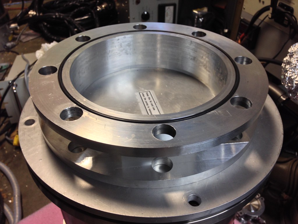
First step is to make a ASA 6" non-threaded to non-threaded flange. To make this I used a 11.25'x2.25" disc of aluminum with a 4" hole in the center I found on ebay. I chucked it up in the lathe and faced one side and then flipped it over and faced the other. I then ran into a problem. I do not have enough travel in the cross slide to cut out the aluminum to create what would be the flanges. I decided I would figure out a way to do that on the mill. Putting that aside I cut the two grooves for the o-rings that will seal this to the valves. If all possible you always want to cut o-ring grooves with a lathe or a trepanning tool, the scratches in the cut will be with the length of the o-ring and create a better seal, milled o-ring grooves can leak. To cut this I used my threading tool holder with a 1/8" wide grooving insert.
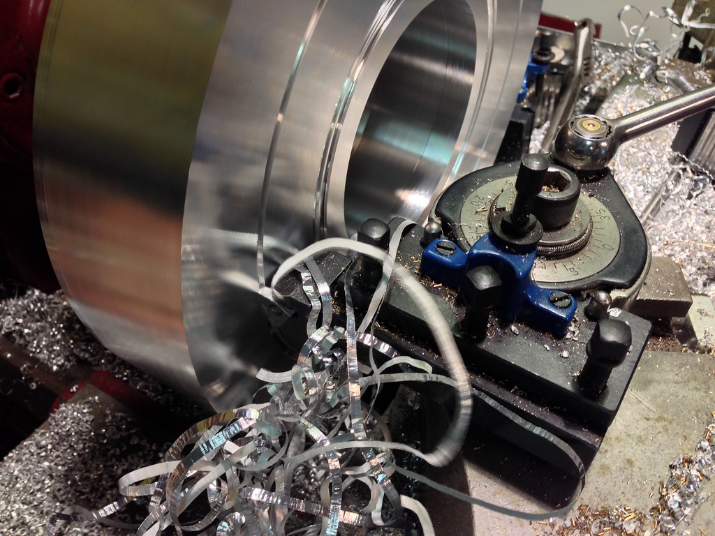
![Untitled]() With that done I put the ring on parallels on the mill table and secured it with a stud to the table. I used the mill to clean up the perimeter of the disc to 11" and then drill eight 27/32" holes for bolts.
With that done I put the ring on parallels on the mill table and secured it with a stud to the table. I used the mill to clean up the perimeter of the disc to 11" and then drill eight 27/32" holes for bolts.![Untitled]() To cut the flanges out I put the disc on edge on the table and use the shortest 1" cutter I had and milled out the groove 1.55" in from the edge at each bolt hole. Finally I clamped it back down to the table and programmed a tool path to cut out the remaining material in the center of the ring which finished this part. Next will be to make another adapter, this one will go from the ISO flange to the ASA flange, but I need more aluminum for that.
To cut the flanges out I put the disc on edge on the table and use the shortest 1" cutter I had and milled out the groove 1.55" in from the edge at each bolt hole. Finally I clamped it back down to the table and programmed a tool path to cut out the remaining material in the center of the ring which finished this part. Next will be to make another adapter, this one will go from the ISO flange to the ASA flange, but I need more aluminum for that.![Untitled]()
-
Turbos and Filament controls
04/29/2014 at 07:11 • 0 commentsWell, the turbo I had hoped would work seems to have a short circuit somewhere in the pump. With no documentation available I dont even know where to start. The plan is to sell this pump and controller as well as another controller for a Osaka Vacuum turbo on eBay and hopefully that will cover the price of the controller for the big pump I have. Then I cross my fingers again that that pump is OK.
I got the little Leybold Turbovac 50 installed on the RGA, this will allow me to sample partial pressures up to 150mtorr in the chamber. I learned some stuff about these little leybold turbo drives in the process. First, and most important, is the cabling. The manual lists 5 wires, three for the phases of the pump, one shield, and one ground. No where in any of the manuals do they mention that this shield is at +160v DC! I had the shield and ground swapped and blew just about every logic IC in the drive. I bought an older NT-50 drive off ebay to replace it and, of course, it didn't work right. I lucked out and Leybold gave me the schematics and waveforms for the drive since they dont repair them anymore and managed to get it working. One open resistor and a bad comparator later and it works.
Next thing is the evaporator control, the big transformer has got to go, it just pulls too much on 120v and the variac that is used to control it cant take that kind of power for long. And then there is the issue with the ground being used as a neutral. Pretty much everything is wrong.
So my solution is using a big old 5v, 600A switching power supply to supply current to the filaments. I am using some big mosfets, some LEM current sensors, and a Teensy 3.1 to create a PID loop controller that should allow me to control the power to all the filaments simultaneously. The boards are made and stuffed, now I just need to program and test.
-
Varian filament controller
03/01/2014 at 08:48 • 0 commentsI pulled out the old Varian Filament controller and tried it out. Didn't work, no output. I popped it open and immediately found one corroded electrolytic dated 1981. Replaced that. Still no workie. Found another bad electrolytic. Changed that... Nothing. Then noticed a broken wire on the local/remote switch, I checked the switch while I was at it and it was not working correctly. Grabbed another and soldered it in place and it worked with a resistive load.
So I hooked it to the transformer. Immediately popped the breaker on the control panel. After doing some checking the transformer pulls way, way too much current for this controller which is basically just a zero-crossing triac dimmer which is rated for 2kw max or about 9 amps at 240. It looks more and more like the transformer is wound for 120v input which wouldnt be so bad but the thing pulls a massive amount of current when running higher currents. At 400 amps out it is pulling 40 amps @ 120v from the wall. That is pretty difficult to deal with.
I think what I am going to do now is use a large switching supply I have, 5v at 400A, and build a mosfet based PWM power control for it and use that. That will eliminate a lot of my electrical problems in the end.
I got the batteries for the turbo control. Need to wire them up and test it out. The batteries are too big to fit internally where the old pack was so I will use the external battery connector to hook them up, it uses a 2 pin "microphone" connector and I am going to try to find one locally tomorrow.
Vacuum System for Deposition
I have been putting a system together for the past few years to do different kinds of deposition.
 With that done I put the ring on parallels on the mill table and secured it with a stud to the table. I used the mill to clean up the perimeter of the disc to 11" and then drill eight 27/32" holes for bolts.
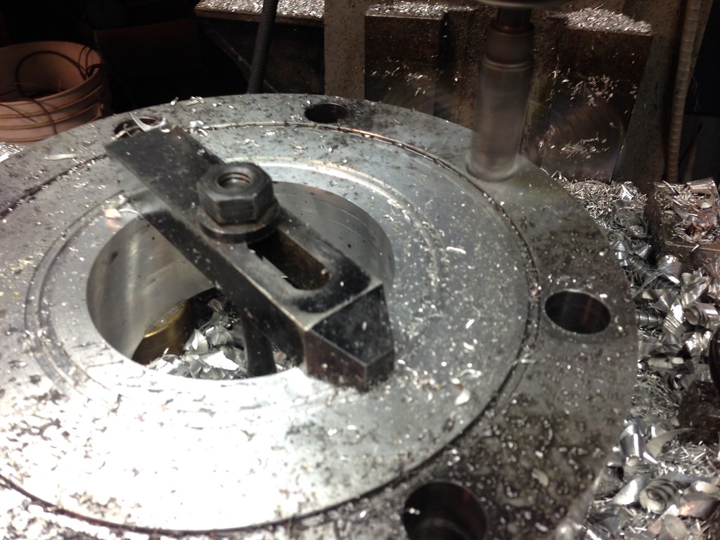 To cut the flanges out I put the disc on edge on the table and use the shortest 1" cutter I had and milled out the groove 1.55" in from the edge at each bolt hole. Finally I clamped it back down to the table and programmed a tool path to cut out the remaining material in the center of the ring which finished this part. Next will be to make another adapter, this one will go from the ISO flange to the ASA flange, but I need more aluminum for that.