 Gabor
GaborAn experiment in accurate timekeeping
In late 2022 ZeptoBars shared an approach in the Sensor Watch community to boost that watch's accuracy through fine calibration and dithered error correction in software. This triggered my curiosity: can I reduce the approach to the bare minimum and build an exceptionally accurate clock using only ordinary components? Here is the result: a clock implemented in 8KB of firmware on an ATmega88V with a 60-cent quartz crystal. The clock is ticking and the experiment is in progress! The CR2032 coin cell battery should power it long enough for us to see how many seconds the clock drifts in a year, with room to spare.
The full source code, schematic, PCB and laser cutter design files are available in the Github repository. Some WIP threads from Mastodon are here and here.
User interface
Just like any old quartz clock, RAQC's user interface consists of a simple LCD display and a few buttons. In its default mode, when it's showing the current time, it looks like this:
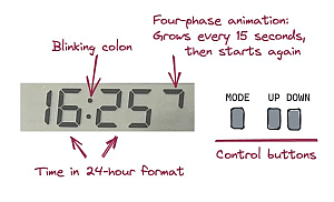
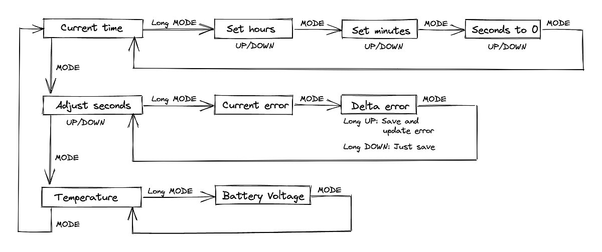
The clock has a set of screens that you can navigate with short and long presses of the MODE button. The settings screens use the UP and DOWN buttons to change values.
Fine-tuning and calibrating
What makes RAQC different from a conventional digital clock is that you can set the time with sub-second precision without the need for good reflexes. Every time you you calibrate this way, RAQC updates the calculated error of its quartz crystal and becomes more accurate.
Here's how to calibrate the clock:
- When you first insert a battery and start the clock, set the current time the usual way on the Set hours, Set minutes and Seconds to 0 screens.
- Then go to the Adjust seconds screen and fine-tune using the method explained below. Long-press DOWN on the Delta error screen to apply the change.
- Wait one or two days, until the clock drifts by up to a few seconds. Go to Adjust seconds and fine-tune. Long-press UP to apply the change and also update the calculated error.
- The clock is now a lot more accurate. Wait a week or two until it drifts by up to a few seconds again. Repeat the previous calibration step. Wait a month or two and re-calibrate.
- Verify the time every once in a while and repeat when the drift becomes noticeable. As the crystal ages, particularly in the first year, it is likely to become slower by about 1ppm per year. You might need to re-calibrate once or twice a year to compensate for this.
Precisely adjusting seconds
To fine-tune the time on RAQC, you need an accurate reference clock that shows seconds updating in real time. The clock on your laptop or cell phone is not good for this purpose, and neither is the time displayed by most websites. All of these update their time regularly so they're never off by a lot, but they're unlikely to be very accurate at any one moment.
Reliable sources of time are specialized websites like time.is; devices that take their time from a GPS signal; or radio clocks that show the time from a long-wave signal like DCF77. The most straightforward of these is time.is.
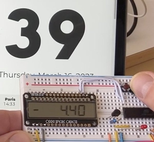
The photo above shows RAQC's Adjust seconds screen. (The photo was taken at the prototype stage, but this works exactly the same in the final build.) "40" on the right is the current seconds value; it keeps ticking in real time. The value to the left of the dot, -4, is the current adjustment. In the background you can see a part of time.is in a browser window, showing the true seconds value of "39". RAQC's time is a bit ahead of the truth, so we want to turn it back a little.
The adjustment value, which you can change using UP and DOWN, is in multiples of 1/32 seconds (31.25 milliseconds). A value of -4 means we're turning back the clock by 125 milliseconds.
Don't worry about the specific numbers you see here. Just keep adjusting up and down until the seconds on your clock and the seconds from time.is are ticking in perfect synchrony. Then press MODE twice to go to the Delta error screen. There, store your adjustment by long-pressing DOWN (the first time you do this) or UP (for every subsequent calibration). When you long-press UP, the Delta error value gets added to the
Current error from the previous screen, making the clock more accurate.
Here's a video of the process:
Circuit design
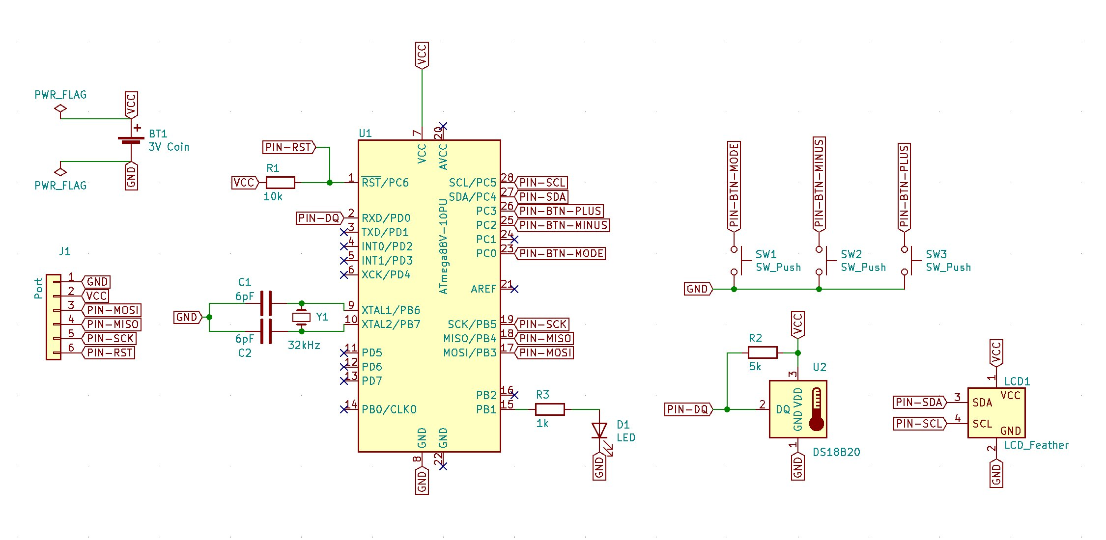
The point of RAQC is to create a remarkably accurate clock from entirely unremarkable, cheap parts. These are the main building blocks:
- A barebones ATmega88V microcontroller. This is a lower-memory sibling of the famous ATmega328P; the two are pin-compatible. You are free to use an ATmega328P if you can find one, but where I am its DIP package version has become unobtainium. The 88V is simply the closest equivalent that I managed to still scrape from the bottom of an online shop. My ATmega88V cost €4.30.
- A DS18B20 one-wire digital thermometer for €3.50.
- A 32,768Hz quartz crystal. These are all cheap, but I went for a slightly more "expensive" one that came with a datasheet showing a temperature error chart. Important detail: the ATmega datasheet recommends using a crystal with a 12pF load capacitance along with a pair of 6pF caps. The part I used is EuroQuartz MH32678B at €0.60.
- Display: LCD Featherwing by Oddly Specific Objects. It is extremely low-power and it is very easy to talk to over an I2C interface (something that's quite rare for simple LCD modules). This was the most expensive single component at $19.95.
- A pair of 6pF caps; 3 push buttons; two resistors; an LED; a pin header. Price negligible.
Hardware
The clock's design emphasizes the raw electronics: it is a PCB enclosed in a transparent laser-cut case. This is what the PCB looks like on its own:
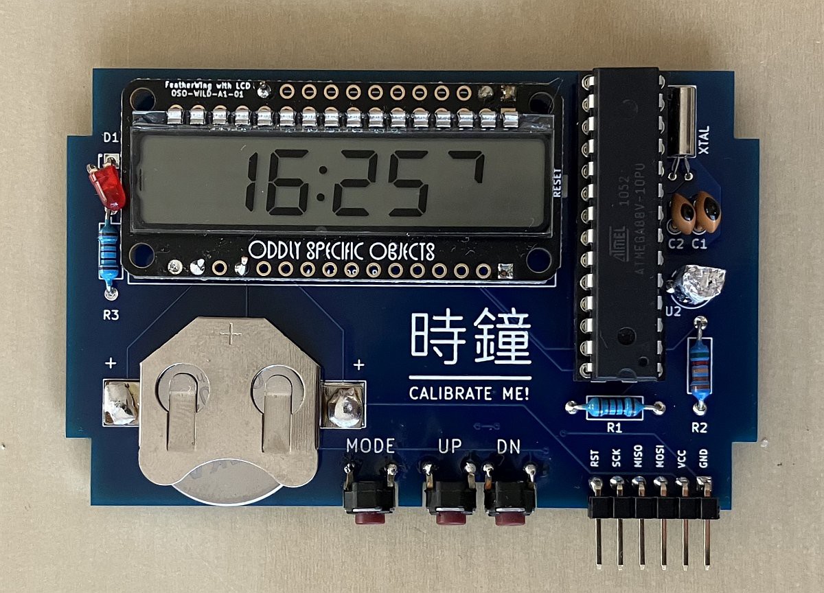
Interesting details:
- The crystal and the caps are placed close to the chip to reduce interference and stray capacitance. In this area, ground plating is added on both sides of the PCB for extra shielding.
- The temperature sensor is wrapped in aluminum foil because the part has a black body, which in direct sunlight might get warmer than the crystal in its metal casing.
- The pin headers at the bottom right make it easy to connect a programmer for future firmware updates.
- The battery holder is a simple solder-on part. You can reach in from the top, under the display, with a toothpick to push the battery out downwards.
Accurate timekeeping with error correction
Quartz clocks like RAQC measure time using a quartz crystal that oscillates at a frequency of 32,768 kHz. Due to small manufacturing differences the frequency of every particular crystal will be slightly off from the nominal value. These tiny differences are measured in ppm (parts per million), which is like a percentage, but in units of one-millionths instead of one-hundredths.
In addition to the static offset of individual crystals, their frequency also varies dynamically with temperature. Crystals are manufactured in a way that their frequency peaks at 25 °C and decreases at both higher and lower temperatures. The diagram below is from the datasheet of the crystal in RAQC:
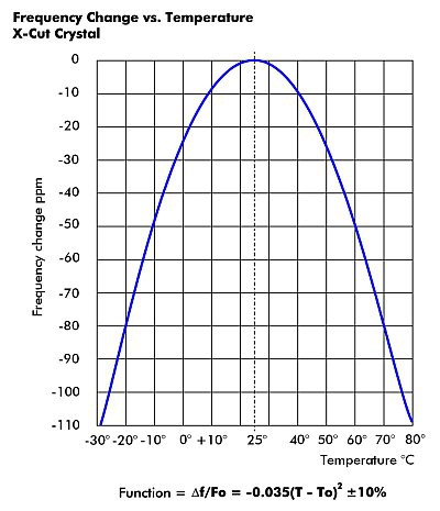
On a hot summer day, with the temperature at 40 degrees, the crystal will be almost 10ppm slower, which would translate to the clock being over 5 minutes slow per year if not compensated for.
RAQC does two things to enhance accuracy:
- It calculates the crystal's static error through a series of fine time adjustments, and subsequently compensates for the known error;
- It measures temperature every 10 minutes and applies a correction to compensate for the dynamic error in each 10-minute period, based on the diagram from the crystal's datasheet.
Implementation in the ATmega
- Timer 2 is set up to use the oscillator with the external quartz crystal.
- A prescaler of 256 is used, and a match compare interrupt gets triggered every time the counter reaches 128. This means the interrupt is fired exactly once per second, on every 128th "beat".
- After each 10-minute period a local error is calculated by summing the static and temperature-dependent components. The result is added to the accumulated error.
- Whenever the accumulated error crosses a threshold, Timer 2's counter is manipulated to make the next second either shorter or longer by a 1/128-second beat.
- In practice, making a second longer by only one beat this way is complicated, so the time is corrected when two beats' worth of error accumulates. Assuming a perfectly compensated clock, its error grows steadily between adjustments, but only ever marginally exceeds 15 msec at the top.
The code implementing this is not very complicated. It resides partly in corrector.cpp, and partly in the timer's interrupt service routine ISR(TIMER2_COMPA_vect) in main.cpp. The timer itself is set up in void setupTimer2() in main.cpp.
Low-power techniques
RAQC is special not only because of its accurate timekeeping but also because it does this in an ordinary ATmega at very low power. These are the techniques it uses:
- The ATmega spends nearly all of its life in power save mode, the low-power mode that only keeps the external oscillator running.
- The processor wakes up once per second. It updates the time in the interrupt handler, and performs one iteration of the main loop to perform tasks that might be needed, like updating the LCD or starting a temperature conversion.
- The ATmega runs at only 1 MHz.
- All unneeded peripherals are turned off. Most importantly, the analog-digital converter (ADC) and the brown-out detector (BOD) are notorious power hogs and must be disabled.
- Outside the transmission when the LCD is updated, the two-wire interface (TWI) is also powered down.
- A full display update involves sending 6 bytes' worth of data over I2C. While the transmission is in progress the processor cannot go to sleep, which has a measurable effect on the clock's energy usage. To make this shorter, the LCD is only partially updated when the only change is the blinking colon or the 15-second animation at the last position.
- The DS18B20 draws a full 1mA while it's converting the temperature, and the conversion's duration depends on the resolution. The RAQC doesn't use DS18B20 at its highest resolution but settles for 10 bits instead. This yields a precision of 0.25°C, and reduces conversion time to under 200msec (versus 750msec at 12 bits).
Current draw measurements
The circuit's current draw is very uneven: it draws a steady low current when the ATmega is in power save mode, interspersed with brief bursts once per second when it wakes up. This is impossible to measure precisely with the multimeter that I have access to, so I created the following setup:
- I powered the circuit from a 4,700uF capacitor. First I fully charged the capacitor by connecting it to the battery; then I inserted a 10k series resistor.
- I waited for the circuit to stabilize, then measured the voltage drop on the 10k series resistor. In this circuit the capacitor smoothed out the once-per-second spikes and I got a voltage drop that was essentially constant.
With this setup I measured an average current draw of 14.3uA, which includes the ATmega and the LCD display.
The measurement above did not include the time when the DS18B20 is active. Going by its nominal current draw of 1mA for 200msec once every 10 minutes, the DS18B20 adds the equivalent of 0.5uA, yielding a combined total of 14.8uA.
I assume, pessimistically, that a CR2032 coin cell battery has a capacity of 200mAh. At 15uA that yields 13,333 hours of operation, which is slightly more than 1.5 years.
Future experiments
Will RAQC achieve the remarkable level of accuracy it was created for? In this case, literally only time will tell. I'll report back every few months, and also when the first battery has been exhausted.
There are also a few additional enhancements/improvements that I'd like to explore.
Calibrate center temperature. The crystal's 25°C center temperature is unfortunately also just a nominal value, and the manufacturer allows a deviation of several degrees. It is possible to empirically determine the center temperature (and verify the overall temperature curve) through a series of experiments where we run the clock at a specific temperature for some amount of time and measure its error. Lacking an expensive temperature-controlled oven this is feasible only if the temperature-stabilized times are short -- so we can rely on the short-time-stable temperature differentials in a normal household. The tiny errors over a short period like 30 or 60 minutes might be reliably measured using the time signal from a GPS receiver. This would be a complicated but not unfeasible process that I'd like to undertake in a future iteration. Through the exposed pins it is possible to replace the timekeeping firmware with one used for determining the center temperature, and the same pins allow receiving the time signal from a GPS unit.
Crystal aging. The crystal's static error is expected to shift negative as the crystal ages. Most of the change happens in the first year, after which a lower, steady change is expected each year. This effect can also be measured, and compensated for in software, by recording each calibration. I plan to add this functionality in an updated firmware after enough time has passed.
More compact form. The current hardware, even on the PCB, retains aspects of a prototype. The main reason is my reluctance to solder small SMD parts. Should I overcome that barrier, an LCD driver and a next-generation microntroller like SAMD21 might allow a smaller form factor and an even smaller power envelope.