Purpose
Emulator of radioactive particle detector is a hardware-software electronic module designed to emulate the counter of ionizing radiation level. For this purpose the emulator includes a pulse counting output to the main controller. Arduino, ESP8266, ESP32, Raspberry Pi, STM32 and others can be used as host controllers. The simulated radiation level and operation mode of the emulator are indicated by light signals on the built-in RGB-LED.
GCemu20_V1 is an inexpensive and useful device for:
- safe and system learning,
- unit testing and development of new devices,
- detection and troubleshooting of running systems, etc.
This module is useful in training, testing, and constructing both indoor and outdoor ionizing radiation power meters in both handheld/pocket and stationary designs. The only thing you need to start using the emulator module is any microcontroller that can count the number of input pulses per unit time on its GPIO, as well as power via micro USB.
Specification
- The module dimensions are 30 x 65 x 10 mm. The ESP12.OLED module without display is taken as the basis.
- True Random Number Generator is a built-in ESP8266 TRNG.
- Power of simulated radiation: 5 modes from 0 to 1.5 µSv/h.
- Powered by AC/DC 5V adapter (not included) via micro USB.
- There are 2.54 mm solder holes on the module board for connecting the console via UART. The console can be used when operating the emulator or flashing the embedded ESP8266 controller in GCemu20_V1.
- The current consumption is similar to the ESP12.OLED_V1 module and is up to 80 mA with WiFi enabled (WiFi and ADC required by TRNG).
- The pulse output GCemu20_V1 is compatible with the 3V3 ACTIVE-LOW logic signal levels.
- The output pulse duration is about 10 µs, similar to the GGreg20.
- Software: NodeMCU/Lua firmware. The emulator code starts automatically after power-up in mode 1 (simulating normal ambient radiation level [18-35] CPM).
Why and who needs the Geiger counter emulator
The main idea of any emulator in the field of DIY electronics is to temporarily, at certain stages, use a virtual substitute component instead of a real module in the process of IoT device development or experimenting / learning to reproduce the operation and characteristics of a real device with high accuracy. The emulator should simplify and speed up development, as well as add convenience in the initial stages of a planned project or performing unit tests.
Geiger counter emulator advantages
- No high voltage
- Simplified learning process
- Lower cost
- No real source of radiation is needed
- The resource of the Geiger-Muller tube does not run out, because it does not exist
- Debugging data in the UART
Emulator users
- Radio amateurs in IoT and DIY microelectronics
- Teachers and students of technological universities
- Research groups and institutes
- Parents and children who are independently learning new technologies at home
- Developers and testers of stationary and/or hand-held dosimeters
- Test laboratories for quality and/or consumer protection
Emulator limitations
Among the known limitations of this method of creating a Geiger counter emulator is the memory size of the ESP826 controller, in which we create in a loop the required number of one-shot timers with random times of firing. Each timer, in fact, is a function that takes a certain amount of RAM. When the timers are fired, the memory is immediately released. The execution of the code we developed resembles a spring, which in a cycle once a minute is sharply compressed and slowly uncompressed within the available memory of the controller.. Thus, the maximum possible number of events generated by our chosen method of generating random events at the emulator output directly depends on the amount of free RAM and the speed of the controller.
Experimentally we found that ESP8266 with NodeMCU firmware and Lua language can confidently generate about 260 events per minute or near 1.5 μSv per hour. This is more than enough pulses per minute for the emulator project and the radiation levels it supposedly registers.
How the emulator works
Embedded software cycles to create a certain number of one-time timers within a minute. Each timer, when triggered, initiates a logic level "1" (ACTIVE-LOW logic) on the GPIO of the emulator pulse output. The duration of the logic level "1" is close to 10 microseconds and is similar to the pulses on the true Geiger counter module GGreg20_V3. The only difference is that GGreg20_V3 can also support 5V logic, while GCemu20_V1 only supports 3V3 logic.
The number of pulses at the emulator output and their corresponding random timers during one minute is set randomly and has a preset range corresponding to the current emulator operation mode. The emulator can operate in one of five radiation simulation modes.
The radiation power modes simulated by the GCemu20_V1 module have been chosen to cover the entire range of tasks in which it may be appropriate to use the emulator:
- Mode 0. No pulses (sensor error simulation);
- Mode 1. Natural background radiation (by default after Power-On Reset);
- Mode 2. Acceptable level;
- Mode 3. Increased level;
- Mode 4. Dangerous level.
After power-up the emulator defaults to Mode 1. To change the emulator mode, press the Flash/D3 button (SW1 on the module board).
The modes are selected alternately by pressing the built-in Flash button: Mode 1 -> Mode 2 -> Mode 3 -> Mode 4 -> Mode 0 -> Mode 1 ...
Each power mode is assigned a different color on the built-in RGB LED, so that the user not only sees the output pulses from the emulator to the host controller, but can also distinguish the current modes of operation:
| Operation mode | Radiation power equivalent | Counts per Minute (CPM) | Flash Color | R | G | B |
|---|---|---|---|---|---|---|
| Mode 0 | 0 µSv/hour | 0 | no flashes black | 0 | 0 | 0 |
| Mode 1 | 0.1 - 0.2 µSv/hour | 18 - 35 | cyan | 0 | 1 | 1 |
| Mode 2 | 0.2 - 0.3 µSv/hour | 36 - 52 | green | 0 | 1 | 0 |
| Mode 3 | 0.3 - 0.6 µSv/hour | 53 - 105 | red | 1 | 0 | 0 |
| Mode 4 | 0.6 - 1.5 µSv/hour | 106 - 264 | magenta | 1 | 0 | 1 |
The true GGreg20_V3 module is equipped with a Soviet SBM-20 Geiger tube. This tube has the following conversion factor [pulses per minute, CPM] to [microsieverts per hour] for Cesium-137 source:
μSv per hour = CPM * 0.0057
Let’s perform the reverse operation to calculate for the radiation ranges the appropriate range of the number of pulses per hour that the emulator would have to generate while operating in a certain mode:
CPM = μSv per hour/ 0.0057
According to statistics collected by IoT-devices LLC, the SBM-20 tube is the most popular among DIY projects, so in the GCemu20_V3 emulator we made a binding of software characteristics to this tube.
The ESP8266 controller's hardware True Random Number Generator (TRNG) is used to ensure true randomness of the pulses at the emulator output.
To enhance the effect of randomness, each minute cycle of the emulator generates not a constant number of pulses, but randomly selects the number of output pulses from the range of values given for each mode in the table above. For example, Mode 1 will generate 18 to 35 pulses per minute and this number will vary randomly each time. Thus, the output of GCemu20_V1 has a random number of pulses randomly distributed in time (within each minute of operation).
The GCemu20_V1 product has built-in, ready-to-use program code. To start working with the emulator, simply supply power via the micro USB port and connect the pulse output to the host controller, which processes the pulses and calculates the level of simulated radiation. Buying this product, the user does not need to program or flash it himself, IoT-devices LLC has already taken care of this.
But if necessary, the user can flash the module with different firmware and use the module at will for other tasks through the UART interface by tools designed for ESP8266. It is known that there are many IoT platforms for ESP8266-based modules, such as ESP-IDF, Arduino, NodeMCU, MicroPython, ESPHome, Tasmota and many others.
Module dimensions, I/O port assignment
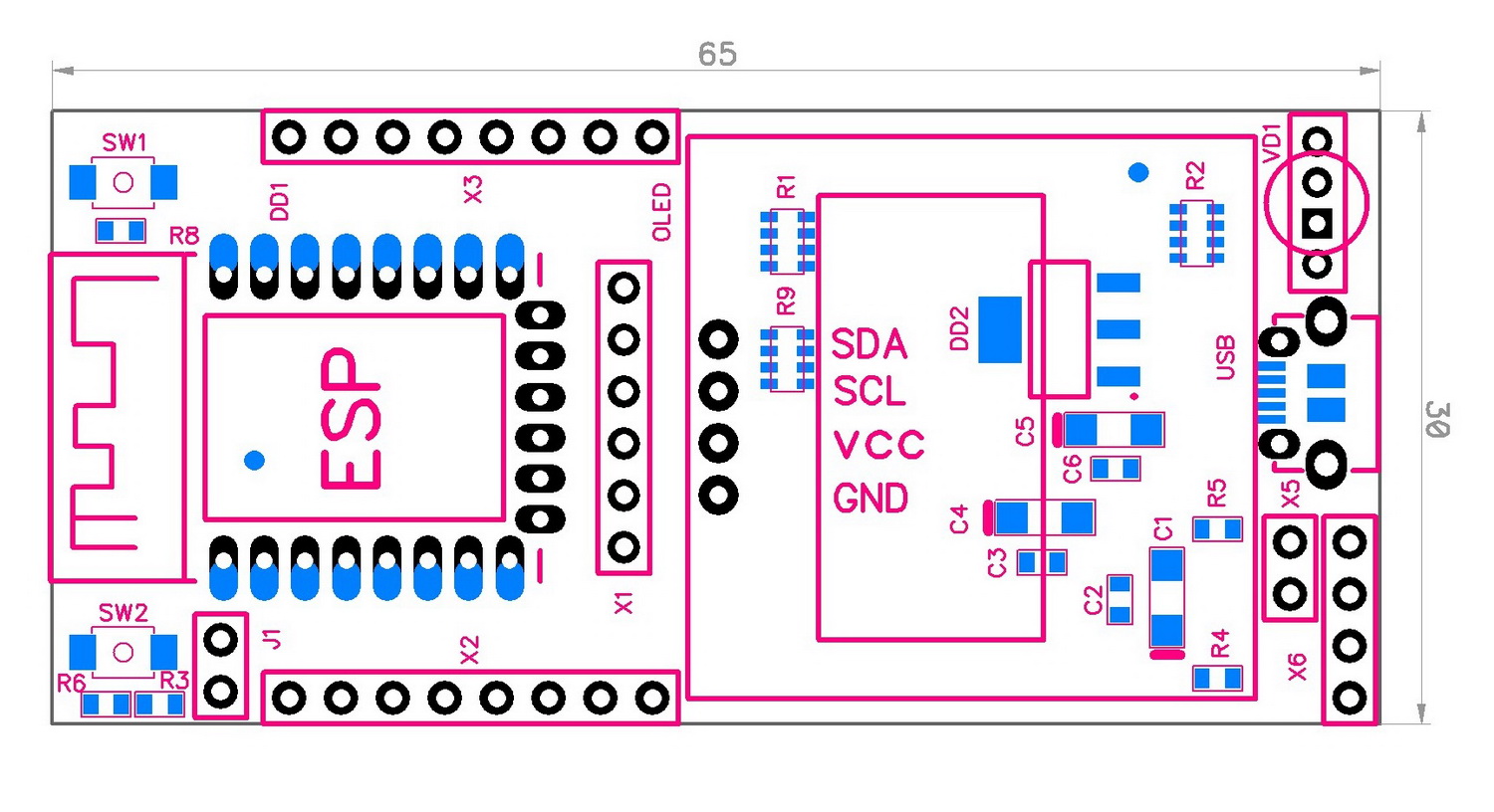
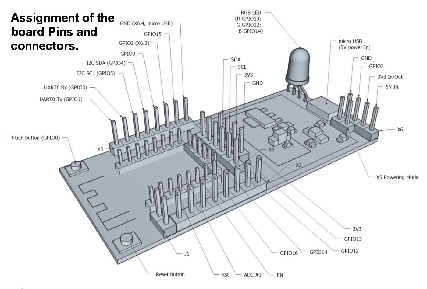
The hardware platform for the GCemu20_V1 uses the universal ESP12.OLED controller module manufactured by IoT-devices LLC, without display. Therefore, the port assignment on the module board corresponds to the documentation of the ESP12.OLED module and the ESP8266 controller integrated in this product.
The printed circuit board of the ESP12.OLED_V1 module:
Assignment of all I/O ports of the ESP12.OLED_V1 module as the hardware platform on which the product GCemu20_V1 Geiger counter emulator is built:

However, only part of the I/O ports available on the ESP12.OLED_V1 controller are used to operate as a GCemu20_V1 emulator.
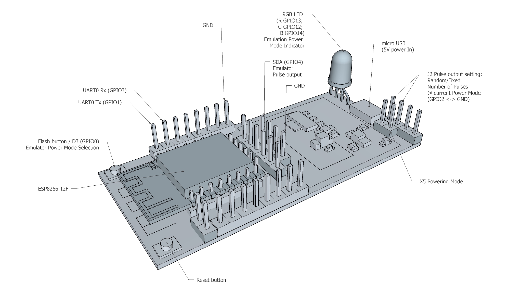
In particular, the GCemu20_V1 emulator uses the following controller ports:
- micro USB 5V power port;
- pulse output of the Geiger counter emulator (GPIO4/D5, marked as SDA on the board);
- UART interface (optional) to connect the developer console:
- UART0 Rx / GPIO3;
- UART0 Tx / GPIO1;
- jumper X5 to select the power supply mode (must be set when power is supplied via micro USB);
- jumper J2 to select the pulse output mode (user setting to switch random number / fixed number of pulses @ current mode of emulation);
- built-in RGB LED:
- GPIO14 / D5 - Blue;
- GPIO12 / D6 - Green;
- GPIO13 / D7 - Red;
- Reset button (marked on the board as SW2);
- Flash button (GPIO0/D3, marked on the board as SW1).
The following figure shows these ports:

Fig. I/O ports ESP12.OLED_V1 (without display) involved in the emulator GCemu20_V1
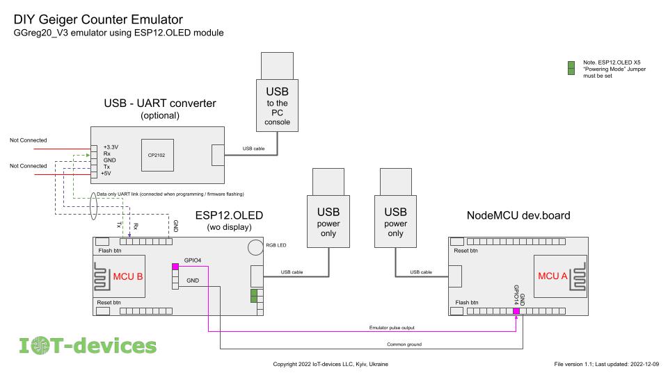
The connection diagram of the emulator module (MCU_B) ESP12.OLED to the main controller (MCU_A) NodeMCU can be as follows:

This schematic also shows the optional developer/programmer console connection via a UART to USB converter.
We recommend the following materials as a reference on port numbering:
- The pin planning and application standard developed by alterstrategy.lab: https://alterstrategy.com/recommended-pin-use-standard/
- NodeMCU flashing documentation: https://nodemcu.readthedocs.io/en/latest/modules/gpio/
- Documentation for the ESP12.OLED module is on the website: https://iot-devices.com.ua/en/product/esp12oled-universal-esp8266-mcuboard-oled-en/
- on Tindie: https://www.tindie.com/products/iotdev/esp12oled-universal-esp8266096oled-mcu-board/
Dimensions of the GCemu20_V1 product built on the ESP12.OLED hardware platform:
- X: 65 mm;
- Y: 30 mm;
- Z: 12 mm.
For comparison, the present Geiger counter module GGreg20_V3 with SBM-20 tube has the following dimensions:
- X: 126 x Y: 30 x Z: 12 mm.
Comparison of GCemu20_V1 emulator and the original GGreg20_V3
| GCemu20_V1 (Geiger counter emulator) | GGreg20_V3 (true Geiger counter) | |
|---|---|---|
| Geiger-Muller tube type | None. Not expected. simulated programmatically | SBM-20 beta, gamma |
| Geiger-Muller tube life | Unlimited | not less than 2*10^10 events per lifetime |
| Maximum theoretical level of detectable radiation | Simulates 5 different modes. From 0 to 1.5 uSv/h. | Limited by SBM-20 tube at 315,780 CPM*0.0057 = 1799.95 uSv/h for Cs-137 source |
| Sensor error simulation | yes, Mode 0 - no pulses (0 CPM) | Not applicable |
| Output the debugging operational data to the console | Yes, via the optional UART interface | Not applicable |
| Consumption, mA | about 80 mA (TRNG requires WiFi) at 5V | 18 mA at 5V or 30 mA at 3.7V from Li Ion |
Switching on and measuring
| !! | This module is only an emulator that simulates a radiation detector, but it is not a real Geiger counter and does not determine the real radiation level. If you are interested in a true radiation sensor, we recommend another product, the GGreg20_V3, which is a real pulse output radiation sensor with a SBM-20 tube as the beta and gamma detector. The GCemu20_V1 emulator module is ready for use. GCemu20_V1 modules are programmed and tested according to the stated specifications before they are shipped. Performing any reprogramming by the customer is possible, but it can damage the module or introduce technical inconsistencies in its operation. Therefore, the user makes any modifications at his own risk. Modules subjected to such modifications are not covered by the return and/or replacement policy. |
It is recommended to switch GCemu20_V1 on as follows:
WARNING: Always remove jumper J2 (GPIO2 <-> GND) before (re)starting the device. GCemu20_V1 will not start unless jumper J2 is removed. This feature of operation is due to the fact that GPIO2, which is connected to jumper J2, takes part in loading the ESP8266 controller and switches it to another mode of operation. At the same time, the jumper works normally after loading the device - it can be removed or installed without restrictions.
Step 1: Connect the input power from the power supply.
Step 2: Turn on the power supply. In no more than 10 seconds you will see light signals on the RGB-LED, simulating a hit of the imaginary particles in the module's detector. On the pulse GPIO output of the module you will see random pulses of 10 microseconds each on the 3V3 ACTIVE-LOW logic according to the set operating mode.
Step 3: Select the required emulator mode with the Flash/D3 button (marked as SW1 on the ESP12.OLED_V1 board).
Product delivery kits
GCemu20_V1 basic
- ESP12.OLED_V1 module (without display) --- 1 pc
- Ready to use, emulator embedded software --- 1 pc.
- 2.54 mm pins kit for self-installation --- 1 pc
 IoT-devices, LLC