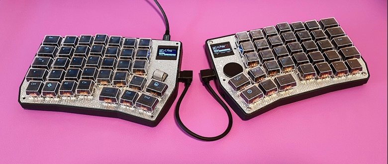
It is finally working! Both sides can be used without modifications! 😁

But that is only for the hardware of course, software is never done as we all know!
Current Software Work
The code is already much cleaner and my current schedule is about testing through the optional devices like rotary encoder, pimoroni trackball and cirque trackpad:
- The rotary encoder works.
- The pimoroni trackball needs a QMK update as it has some issues in my version (the cursor becomes very shaky). To be done soon...
- The 23mm cirque trackpad works after resoling some configuration issues. It is a bit small, so I might try the next size as well.

Open Software Issues
- The status display on the right side (slave) turns on unexpectedly after the turn-off timeout (just resolved minutes ago, so this is also done)
- An issue I had in the past: RGB LED matrix flickers on the master side. Maybe because I changed the LAYOUT macro to reflect the key orientation..? Need to check if I have to do the same for the led_config.
- Easy way to configure the layout. Right now I still have to flash the firmware every time, but at some point I would like to switch to something like Vial so that can be done without flashing anything.
- Some more Icons for all the special function keys.
So you see, there is still plenty of work left.
Further Software Improvements Ahead
- This is out of scope for now but definitely the goal: To have a program on the host side to switch the OS input language and also send program context information to the keyboard so that customized symbols can be displayed.
- To avoid burning out the OLED displays, I plan to shift the displayed content slightly once a while. This is nothing fully developed yet, more an idea.
Final Touches
The PCB is in a production ready state, however I would like to apply a cosmetic change to the silkscreen (some pin markings are on the wrong side - luckily only on the silk screen).
And this is more about the general mechanical design:
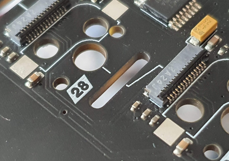
If possible, I would like to have some plastic inserts for the flex cable slots:

With that, the edges would be soother and make the flex cables maybe life longer. I had no such issue so far and the edges are not rough, but if it is possible, I'd like to try. It sounds like an improvement to me. I was also thinking about plated slots, but these have size limitations which makes it impossible (at least at JLCPCB).
Layout
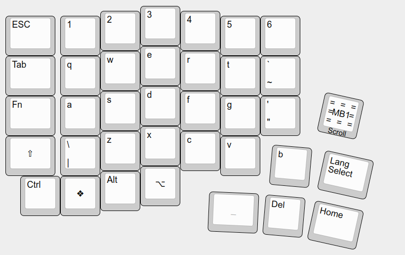
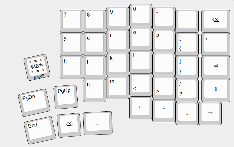
Of course everyone can come up with an own layout, but let me quickly show off my current choice (and might change soon again):


I started with a symmetric layout similar to Ergodox. With the number keys 1~5 on the left side and 6~0 on the right and in a similar fashion distributed the letters.
However, I'm really used to the traditional stagger and there, the left and right hand finger assignment is distributed rather un-symmetrical. Maybe this changes at some point, but for now this layout is much easier to type!
Your perfect layout might look different... let me know in the comments below~
 thpoll
Discussions
Become a Hackaday.io Member
Create an account to leave a comment. Already have an account? Log In.